|
|
|
|
|
|
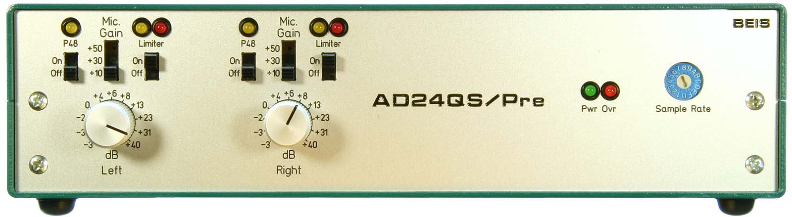
I designed this dual channel audio preamplifier as an appropriate preamplifier for the high quality Audio Analog to Digital Converter AD24QS. It is, of course, easy to build a much smaller and much cheaper preamplifier with comparable functionality, but making it cheap and small was not my goal. A slightly modified version of the AD24QS is piggyback mounted on the preamplifier's board and together they fit into a 200 x 100 x 50 mm³ enclosure (Fischerelektronik SG210).
|
|
|
|
|
|
|
I wanted to test the design of a dual channel preamplifier intended to be used in conjunction with the AD24QS with the following features:
The design goal was definitively not a cheaper preamplifier than commercially available ones - it is designed to be a better one. As a consequence, even as a kit, it is expensive!
The fully balanced design is more expensive than a single ended one, of course, but it has advantages: No (or 40 dB less) hassle with ground loops, crosstalk by common grounds, hum or switching noise caught by ground etc.. Also the maximum internal signal level can be increased by 6 dB which may help to increase the dynamic range under certain circumstances. Note that for a single ended design by far not half of the circuitry can be saved: In order to de-balance input signals and re-balance them for the outputs again, actually 2 op-amps (one dual op-amp) per channel could be omitted only(!).
The 2ChPre is a high quality dual channel preamplifier designed to operate in conjunction with the Audio Analog to Digital Converter AD24QS. It is available as kit for DIY (Do It Yourself). It features:
| Inputs |
2 x Line Input, 1/4" TRS 2 x Microphone Input, XLR |
|
| Outputs |
Digital Audio Outputs in conjunction with AD24QS Monitor: On-board Stereo Cinch (RCA), single ended Option: External XLR, Balanced |
|
| Output Impedance |
On-Board Monitor Output: 100 Ω Optional Balanced XLR Output: 200 Ω |
|
|
Nominal Output Level, Analog and Digital |
On-Board Monitor Output: -2 dBu (615 mVRMS) Optional Balanced XLR Output: +4 dBu (1.23 V RMS) Digital Audio Outputs: 25% FS (i.e., 12 dB Headroom) |
|
| Maximum Analog Output Level |
On-Board Monitor Output: -2 dBu (3.1 VRMS) Optional Balanced XLR Output: +18 dBu (6.2 VRMS) |
|
| Line Input Impedance |
18 kΩ Differential Mode 4.5 kΩ Common Mode |
|
| Line Input Gain Range | -3 dB to +40 dB (i.e., Nominal Input Level = +7 dBu to -36 dBu) | |
| Line Input Noise (@ Gain = 40 dB) |
-110 dBu (2.5 µVRMS), 20 Hz -
20 kHz, Unweighted Option: -113 dBu (1.8 µVRMS), 20 Hz - 20 kHz, Unweighted |
|
|
Line Input Dynamic Range via Digital Audio Output |
108 dB FS @ Gain = 0 dB, 20 Hz - 20 kHz,
Unweighted 104 dB FS @ Gain = 20 dB, 20 Hz - 20 kHz, Unweighted 86 dB FS @ Gain = 40 dB, 20 Hz - 20 kHz, Unweighted |
|
| Line Input THD |
0.0003% @ UIn = UOut = +9 dBu, Gain = 0 dB: -110 dB
(Best Measured Value) 0.0009% @ UIn = UOut = +4 dBu = -12 dB FS (Nominal Level), Gain = 0 dB 0.0008% @ UIn = -16 dBu, UOut = -12 dB FS (Nominal Level), Gain = +20 dB 0.0055% @ UIn = -36 dBu, UOut = -12 dB FS (Nominal Level), Gain = +40 dB |
|
| Crosstalk @ 1 kHz |
L → R: -122 dB R → L: -125 dB |
|
|
Frequency Response Line Inputs (-3 dB) |
1.5 Hz - 1 MHz @ Gain = +0 dB 1.7 Hz - 300 kHz @ Gain = +20 dB 3.5 Hz - 95 kHz @ Gain = +30 dB 10 Hz - 40 kHz @ Gain = +40 dB Option: Up to 250 kHz approx. @ Gain = +40 dB |
|
| Microphone Preamplifier Input Impedance |
4.4 kΩ Differential Mode 1.1 kΩ Common Mode |
|
| Microphone Preamplifier Gain | Switchable +10 / +30 / +50 dB | |
| Microphone Input Gain Range | +7 dB to +90 dB (i.e., Nominal Input Level = -3 dBu to -86 dBu) | |
| Microphone Input Noise |
-112 dBu (2.0 µVRMS) @ Microphone
Gain = +10 dB -126 dBu (0.40 µVRMS) @ Microphone Gain = +30 dB -131 dBu (0.22 µVRMS) @ Microphone Gain = +50 dB |
|
|
Frequency Response Microphone Inputs (-3 dB, Line Gain = 0 dB) |
4 Hz - 700 kHz @ Mic. Gain = +10 dB 4 Hz - 700 kHz @ Mic. Gain = +30 dB 10 Hz - 400 kHz @ Mic. Gain = +50 dB |
|
| Limiter Levels |
Threshold (no Attenuation): +7 dBu (-9 dB FS) 20 dB Attenuation: +9 dBu (-7 dB FS) Attenuation Range (Condition: Line Gain > +14 dB): > 30 dB |
|
| Limiter Timing |
Attack Time, 20 dB Overdrive: 3 ms. approx. Decay Time from 20 dB Overdrive: 400 mS Latency (Step from -17 dB to +3 dB Overdrive): 6 ms approx. |
|
| Power Supply |
12 V DC, max. 700 mA approx. Power supply jack 6.3/1.9 mm (DIN 45323) |
|
| Board Size | 191.44 mm x 88.27 mm (7.537" x 3.475") |
The data above is measured at my sample and cannot be guaranteed, of course.
 Each
channel provides:
Each
channel provides:
On the AD24QS there is:
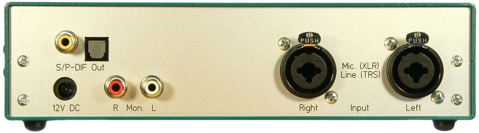
The microphone input is an XLR receptacle, the line input a 1/4" TRS jack, both combined in one XLR / TRS hybrid chassis connector.When the TRS connector is plugged, the microphone preamplifier is disconnected automatically.
The nominal output level of the analog, unbalanced Cinch- (or RCA.) on-board monitor output is -2 dBu (615 mVRMS). As options balanced (XLR-) outputs with a nominal level of (+4 dBu = 1.23 mVRMS) can be connected. See the DIY section for details.
(Note: These outputs are part of the add-on A/D-converter, my AD24QS.) Both digital audio outputs, the optical and the unbalanced Cinch output, can be used simultaneously. The Cinch output is galvanically decoupled by a digital audio transformer. Also as an option a third, e.g. balanced (XLR- or AES-3-) digital audio output with its own digital audio transformer can be connected externally.
I do not provide enclosures. Particularly the front and the rear panel are, in these small quantities, quite expensive. I cannot stock and sell them under these circumstances. But you can directly buy them from a special service I prepared them for. Have a look in the DIY section for more information.
For the current circuit diagram of the 2ChPre, have a look at either the GIF-file or the PDF-file.
The microphone preamplifier uses a standard balanced amplifier IC (INA103) from TI (formerly Burr Brown). This is the only mic-preamplifier which provides balanced outputs (as far as I know), and it features real good technical data. I provided three different gains of +10 dB, +30 dB and +50 dB. Low gains are needed for sources with high output levels, but they produce significantly more noise than high gain stages. Together with the subsequent line amplifier the total microphone gain range is +7 up to +90 dB, by far enough, but not too much for a microphone input. I did not provide an input pad as it is unlikely that the preamplifier will ever be overdriven and, moreover, I do not appreciate pads as they introduce quite a lot of noise.
An input protection is provided with a usual diode network, but not, as usual, with the diodes connected to the supply rails, but connected to lower, zener diode stabilized voltages. This is because the protective series resistances are so low (15 Ω, in order to avoid resistance noise) that quite high currents can flow through the diodes and might cause too high voltage drops across them, so that the protective effect might be reduced or lost in case the diodes would be connected to the power supply rails .
Originally I wanted to design a very low noise microphone amplifier for 20 dB gain. This is not just easy. My efforts ended in the article Extreme Low Noise Preamplifier and once you see that result, you'll understand why I stepped back to this standard IC solution. You also learn there why each low gain microphone preamplifier more or less inevitably generates more noise than a usual (200 Ω) dynamic microphone.
As input connector for microphone and line signals I used a Neutrik NCJ9FI-V, an XLR / TRS hybrid chassis connector combining 3 pole XLR receptacle and 1/4" TRS jack (German readers: TRS or "tip, ring, sleeve" = 6,35 mm Stereo-Klinkenbuchse). When the TRS connector is plugged, the microphone preamplifier is automatically disconnected.
The stage order of the line input amplifier chain is chosen for an optimum of dynamic range and low noise over the whole gain range.
The input stage is a buffer for the subsequent limiter LDR. The series resistors for the LDR divider (2 x 2.7 kΩ) are chosen as a compromise between generated resistor noise and maximal attenuation. A 2.7 kΩ resistor generates approximately as much noise as the input op-amp (OP2134) and with minimum LDR resistance of 300 Ohm approx. it allows a gain variation of more than 20 dB. Not very much, but sufficient under normal circumstances. Moreover, these 20 dB can be achieved only when the subsequent stage's gain is high enough, as otherwise the input stage will clip earlier than 20 dB attenuation takes place.
 The second
stage is the variable gain stage. Its gain is adjustable from
+3 dB up to +46 dB, i.e., the control range is 43 dB.
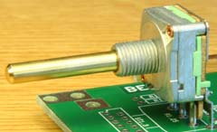
I chose a negative logarithmic potentiometer with 11 detents.
Detents help very much to select reproducible settings, though
a rotary switch with as much positions as possible (e.g., 24)
would be much nicer - but exorbitantly expensive. By using a negative
logarithmic potentiometer the potentiometer's dB-scale is closer
to linear compared to the one from a linear potentiometer, though
it is still quite fare away from being really dB-linear. The potentiometer,
by the way, has a die cast, fully closed metal housing, metal
shaft and is an exact reproduction of the formerly in Germany
very popular Preostat 16 manufactured by the Preh company.
The second
stage is the variable gain stage. Its gain is adjustable from
+3 dB up to +46 dB, i.e., the control range is 43 dB.
I chose a negative logarithmic potentiometer with 11 detents.
Detents help very much to select reproducible settings, though
a rotary switch with as much positions as possible (e.g., 24)
would be much nicer - but exorbitantly expensive. By using a negative
logarithmic potentiometer the potentiometer's dB-scale is closer
to linear compared to the one from a linear potentiometer, though
it is still quite fare away from being really dB-linear. The potentiometer,
by the way, has a die cast, fully closed metal housing, metal
shaft and is an exact reproduction of the formerly in Germany
very popular Preostat 16 manufactured by the Preh company.
The third stage balances the signal and attenuates it by 6 dB. Its resistors should be as precise as possible because they determine the stage's CMRR (common mode rejection ratio). With 1% resistor tolerances at least 40 dB, while with 0.1% at least 60 dB CMRR can be expected. This balancer stage is also the line and ADC output stage. Its nominal output level is +4 dBu (1.23 VRMS, the standard professional audio level). The ADC connected here is dimensioned to convert +4 dBu to -12 dB FS (-12 dB Full Scale, i.e., 1/4 of the ADC's full scale range). The maximum output level available at the line outputs connected here is +18 dBu (6.2 VRMS). Note: This balanced line output is an option, to be connected externally e.g. to XLR connectors and it is not included in the kit.
The line input amplifier's total gain range is from -3 dB up to +40 dB. At minimum gain (-3 dB), with the ADC's conversion factor of -12 dB FS at +4 dBu, the nominal input level is +7 dBu and the digital clipping level is +19 dBu (6.91 VRMS). At maximum gain (+40 dB), the nominal input level is -36 dBu (12.3 mVRMS approx.).
A pair of unbalanced monitor outputs with Cinch (RCA) jacks is provided. Their output voltage is always 1/2 of the line output voltages mentioned here.
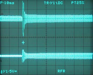
The limiter is meant as a kind of "emergency break" to prevent the ADC from being overdriven in case unexpected, very high amplitudes occur. It is designed to be fast, with short attack and decay time.
One of the major issues of limiter design is the latency of its response. Latency means the time until any response is visible in case of an overdrive following silence. In each design a buffer capacitor must be charged by the signal and the limiter sets in, when a certain threshold is exceeded. Until this threshold is reached the signal remains unlimited, and this can become quite an unwanted while, particularly when charging starts from zero (silence) and rises only slowly (slight overdrive). In a well designed circuit the limitation must take place as early as possible, even after silence and slight overdrives. This requires the threshold to be formed in the AC part, prior to the rectifier, so that the DC threshold can be almost zero. In my circuit the limiting threshold results from several diode threshold voltages mainly, while the buffer capacitor(s)'s voltage needs to rise less than 10 mV only until limitation sets in.
|
|
|
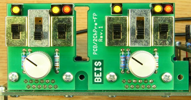
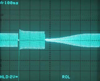
The limiter, when enabled, has a threshold of about +7 dBu (1.7 VRMS, -9 dB FS) and limits to about +9 dBu (2.2 VRMS, -7 dB FS) in case of an input level 20 dB higher than the threshold. Note, the ADC clips at +16 dBu. I.e., output levels of up to 3 dB approx. above nominal level of +4 dBu are not influenced by the limiter and the limiter's highest output level will remain 7 dB below 0 dB FS of the ADC. A red LED indicates when the limiter is active. (Another red LED on the ADC indicates when 0 dB FS are exceeded - with or without the limiter.)
I chose a low distortion LED optocoupler (3WK 163 43 from Tesla Blatna) as attenuation control element, because, as long as they are passive, they will not affect the signal quality at all. Due to its much higher dynamic range and other features the Analog Devices SSM2018T (or two of them, for a balanced design) would probably be the best choice for a purely electronic solution. This device has excellent technical data, but it will always impact the signal much more than a passive (i.e., non-conducting) LDR optocoupler and with it, the specifications currently achieved by far cannot be maintained any more.
The limiter's full range of 20 dB can only be achieved as long as the input stage is not overdriven, i.e., when the line amplifier is set to a gain of +4 dB approx. or more. With 0 dB gain, the limiter's range is reduced to 16 dB approx. (i.e., the maximum input level of +24 dBu is limited to an output level of +8 dBu approx.).
A push-pull voltage converter with a self wound RM5 transformer generates from the +12 V supply slightly less than -12 V (called "-12V", though) and +67 V approx., which is regulated to +48 V for the phantom supply. The analog supply voltages +11V and -11V (actually rather +10.8 V and -10.3 V) are filtered by two ripple smoothing voltage followers so that the design is quite tolerant against noisy power supplies.
My ADC AD24QS is populated slightly different to the one I published as a stand-alone version. The differences are: The input stage's gain is modified so that the sensitivity is reduced to +16 dBu @ 100% FS (12 dB above nominal professional audio level), instead of the RCA input jacks a 16 pin Micro-Match connector is used for audio signals and power supply. Great portions of the power supply circuitry are omitted as the ADC is supplied with positive and negative voltage by the preamplifier. These differences are noted in the ADC's circuit diagram. Here you find it either as GIF-file or PDF-file.
 For different
reasons I sell these converters as kits and thus for DIYs only.
For different
reasons I sell these converters as kits and thus for DIYs only.
I expect sufficient experience from people to assemble the kits. I don't explain how to read resistor values, how to discriminate a 100 µH inductor from a 100 Ω resistor, which components are polarized, on which side the soldering iron gets hot and so on.
What even happens to me is that I mix up similar looking resistors, place components in the wrong places or rotate ICs by 180°. Usually all this soon becomes quite obvious and can easily be corrected.
One difficult thing I believe I cannot trust somebody to do by himself is to wind the RM5 transformer. I do not know readily available transformers for this application, so I had to design and wind it myself. That's DIY. It took me quite a couple of tests with various cores and various winding schemes until I got to the final version. Though I made myself utilities to ease hand-winding and I believe to be experienced in hand-winding such small inductors, again I broke some coil formers. I.e., I do not recommend to do it yourself. I'll wind the transformers for you. It costs me quite a time, but I do not see any other reasonable way to overcome this problem.
I'll also prepare the Micro-Match cable. Though it looks simple, without knowing how to do it and without experience you'll probably destroy the connectors when trying it for the first time. I payed for this experience - you shouldn't.
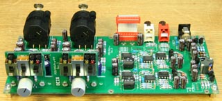
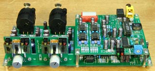
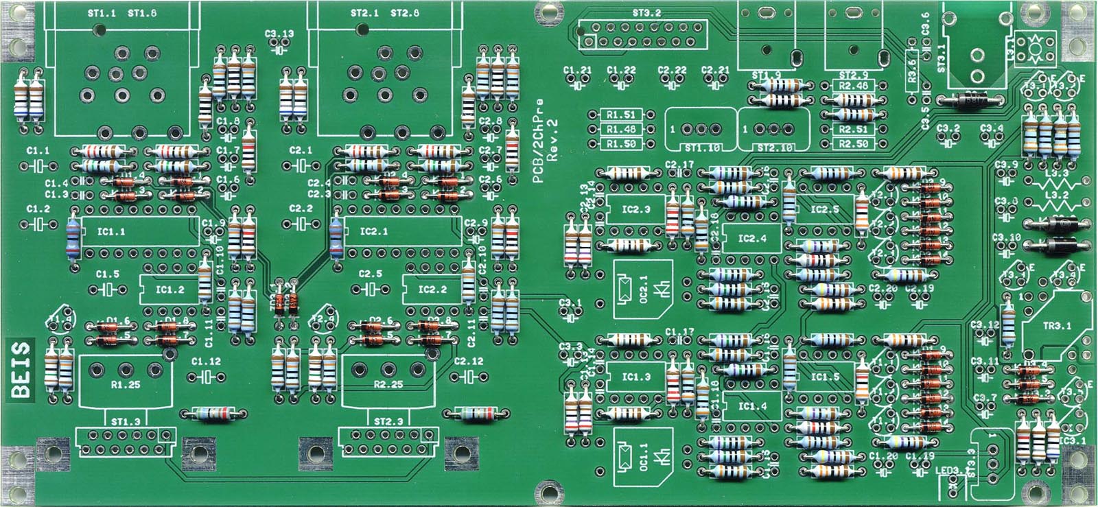
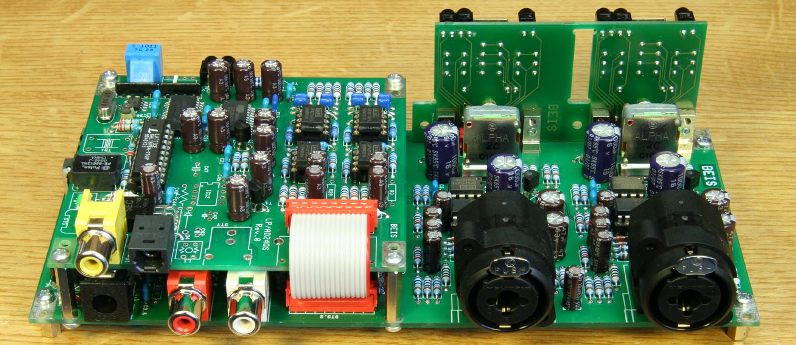
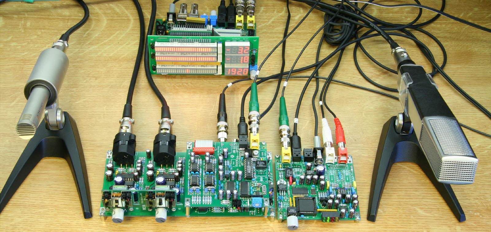
The kits I provide come with all necessary electronic and mechanical parts for the basic version of the preamplifier, the 2ChPre-K (i.e., without balanced audio outputs). The kits also come without an enclosure, front or rear panel but include two 12 mm aluminum knobs . It is just as you can see on the photos, except for the IC-sockets and the four stand-offs with their screws visible there.
See the BOM (bill of material) for the 2ChPre and the AD24QS (version for 2ChPre) for what is actually included in the kits.
Find here the assembly drawings:
|
|
|
| Indicating the component names | Indicating the component types or values |
|
|
|
| Indicating the component names | Indicating the component types or values |
 Normally
all axial components, i.e., resistors, diodes and inductors, come
cut and bent. This saves a lot of assembly time for you and may
help that the assembly looks neater.
Normally
all axial components, i.e., resistors, diodes and inductors, come
cut and bent. This saves a lot of assembly time for you and may
help that the assembly looks neater.
Not all components on the board need to be populated. They are partially intended for options. Which one is to be populated and where is shown in the assembly drawings.
2 jumpers, indicated red in the assembly drawing, must be placed instead of L3.1. For these slightly longer wires (5 mm) I prefer colored insulated ones because it looks better.
Balanced Outputs: I can offer a set of components including the passive components, the Micro-Match connector and the appropriate ribbon cable.
Improved Line Input Performance: With a set of 4 significantly better dual op-amps LM4562 instead of OPA2134 (IC1.2, IC1.3, IC2.2, IC2.3) several improvements are possible:
All of these improvements take place at high line amplifier gains only, i.e., the values above refer to +40 dB line gain. They have not been measured but calculated, except for THD.
EMC choke: For an improved EMC (electro-magnetic compatibility) the board is prepared for a common mode choke, L3.1 in the power supply input. I pay attention to EMC performances but I am not able to test them. I prepared the choke "just in case". Under normal circumstances it is not required.
Anyway, the Preamplifier should always be installed into a well shielding enclosure!
Options for AD24QS: See article AD24QS
I don't regard IC sockets to be necessary, but as I usually make experiments with my prototype devices, I use them there. This is why you see sockets on my photos, but they are not included in the kits.
The ADC is mounted piggyback on the preamplifier's PCB using four 17.5 mm, M2.5 thread bolts and connected by a 16 wire Miro-Match cable, as can be seen on the photo.
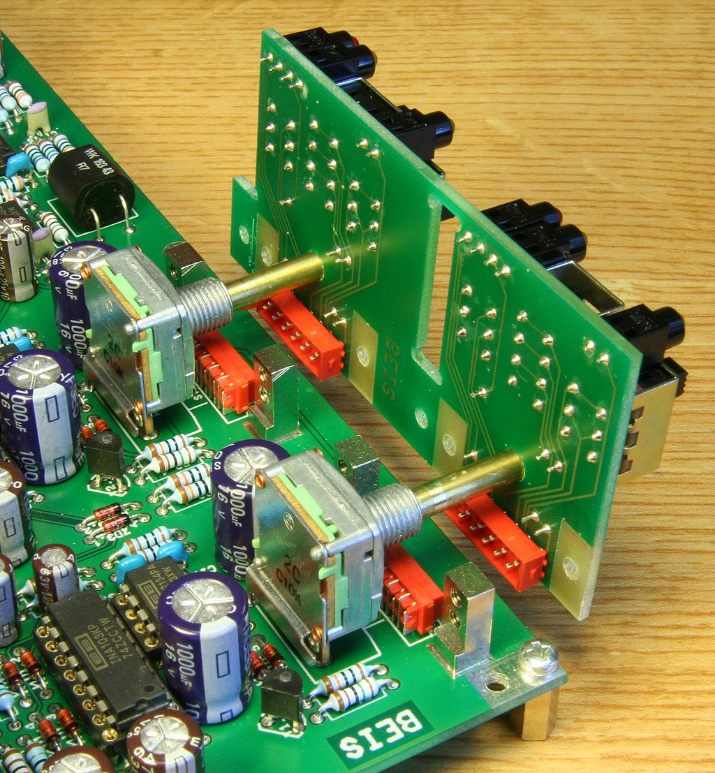
The front panel board is screwed sturdily to the mainboard by 4 mounting blocks and can easily be unscrewed and unplugged from the mainboard. The front panel PCB also guides the potentiometer's shafts.
 For
my units I used an SG210 enclosure from the (German) company
Fischer Elektronik. Front panel, enclosure
and board are directly fixed to each other using the element 5.60.422 from the (German) company
Ettinger,
available at Bürklin. You need not necessarily use
the enclosure I used. The board can easily be built into other
enclosures. For this enclosure I provided a detailed dimensional
drawing, either as a GIF
file or as a PDF
file. You will see there how the board is fixed within the
SG210 and how it can alternatively be fixed directly to other
front panels. Of course you may also use four stand-offs, distance
bolts or distance tubes to fix the board on the bottom of your
enclosure. The drilling positions can be found in the dimensional
drawing, too.
For
my units I used an SG210 enclosure from the (German) company
Fischer Elektronik. Front panel, enclosure
and board are directly fixed to each other using the element 5.60.422 from the (German) company
Ettinger,
available at Bürklin. You need not necessarily use
the enclosure I used. The board can easily be built into other
enclosures. For this enclosure I provided a detailed dimensional
drawing, either as a GIF
file or as a PDF
file. You will see there how the board is fixed within the
SG210 and how it can alternatively be fixed directly to other
front panels. Of course you may also use four stand-offs, distance
bolts or distance tubes to fix the board on the bottom of your
enclosure. The drilling positions can be found in the dimensional
drawing, too.
The front panel is manufactured by Schaeffer AG (in Europe) and is available in the US from Front Panel Express, LLC, too. You need the design files for the front and the rear panel, then you just have to send it to the manufacturer and you'll get a perfectly milled and engraved front panel, as the photos show. You may also modify the design file with the front panel design software "Front Panel Designer" German or English (it's free and very convenient) so that it fits to other enclosure of your choice.
All companies mentioned above have international branches, e.g. in the USA.
I made all measurements on my only sample and I believe to have done that correctly. All measurements are made through the preamplifier's ADC, hence they include the ADC's performance.
Actually, my low distortion generator (Hameg HM8037) is specified with significantly more distortion than the values I measured for the whole system. I.e., my generator must be much better than specified. Though due to the specification of the HM8037 (THD < 0.01%) hardly believable, the following measurement (or, to be carefully, "readings") are true:
A THD of 0.0003%, i.e., 1/30th of the generators specification, is not only excellent for the generator but very good for the preamplifier, too. This measurement is taken at with 0 dB gain at an optimal in- and output level of -7 dB FS. At other levels the measured values are not that good:
Measured with the inputs shorted, 20 Hz. -20 kHz, unweighted:
The dynamic range is the negative value of the output noise referred to 100% FS, i.e., +108 dB to +86 dB in the measured examples above.
The input noise can be derived from the conversion factor, gain and output noise at high gains and is 86 dB + 40 dB = 126 dB below the input sensitivity for 100% FS @ gain = 0 dB (= 16 dBu = 4.92 VRMS). I.e., it is -110 dBu or 2.45 µVRMS. For the actual circuit design can be awaited: The Noise of 4 x OPA2134 (= 8 nV/(Sqr(Hz) each) + 2 x 1 kΩ + 2 x 2.7 kΩ = 2.73 µV. Quite plausible measured results. With 4 of the significantly more expensive dual op-amp LM4562 (= 2.7 nV/(Sqr(Hz) per op-amp) 1.74 µV input noise can be expected, a considerable improvement of almost 3 dB.
In order to determine the microphone input's noise the output noise of the preamplifier was measured with the microphone inputs shortened:
@ Line Gain = +0 dB, unweighted:
@ Line Gain = +40 dB, unweighted:
Once again, the dynamic range is the negative above value. By the same way described above the input noise can be derived and is:
The awaited value for a microphone Gain = +50 dB is the noise of 1 x INA103 (= 1 nV/Sqr(Hz)) + 2 x 15 Ω + 1 x 20 Ω = 0.20 µV. Once again the measured results are plausible. The resistive noise of a usual (200 Ω) dynamic microphone is 0.26 µV. It is increased by the microphone input amplifier's noise @ +50 dB gain to 0.33 µV, i.e., by 2 dB only.
All noise values above are measured and indicated unweighted. Because it is almost pure white noise, the values become "better" by another 2 dB when they are measured A-weighted.
The frequency responses are measured at the balanced line or unbalanced monitor outputs of the preamplifier - not through the ADC.
1.5 Hz - 1 MHz @ Gain = +0 dB
1.7 Hz - 300 kHz @ Gain = +20 dB
3.5 Hz - 95 kHz @ Gain = +30 dB
10 Hz - 40 kHz @ Gain = +40 dB
At gains of +40 dB the upper frequency limit becomes quite low, 40 kHz approx.. This is due to the finite GBW (gain-bandwidth) product of 8 MHz of the 2nd stage's OP2134: 46 dB gain is a factor of 200, and 8 MHz / 200 is 40 kHz, exactly what I measured. Using once again the superior, but significantly more expensive dual op-amp LM4562 (GBW 55 MHz, though unity gain stable) should increase the upper frequency limit at gains of +40 dB to up to more than 250 kHz(!).
4 Hz - 700 kHz @ Mic, Gain +10 dB, Line Gain
= 0 dB
4 Hz - 700 kHz @ Mic, Gain +30 dB, Line Gain =
0 dB
10 Hz - 400 kHz @ Mic, Gain +50 dB, Line Gain =
0 dB
Measured using the line inputs, gain = 0 dB, one channel input shortened, other channel @ 100% FS.
These unusual good values are obviously a consequence of the fully balanced design.
The nominal power supply voltage is 12 V DC and should be abided within +/- 0.5 V.
Current consumption:
This kit is no longer available unless somebody needs quite a lot of them. In this case please write me an e-mail. Also in this case slight modification would be possible.
... was a nice experience... :-)
| Last update: October, 23th, 2013 | Questions? Suggestions? Email Me! | Uwe Beis |