|
|
|
|
|
|
|
DA24QS and DA24DS - Audio Digital to Analog Converters 24 Bit / 192 kHz (96 kHz) instead of this one and, in case, delete the link to this article! |

The DA24QS is a high quality Audio Digital to Analog Converter available as kit for DIY (Do It Yourself). It features:
| Sample Rate Range | 30 - 216 kHz | |
| Digital Audio Inputs |
2 x on-board optical (Toslink, up to 96 kHz only) 1 x on-board coaxial Cinch (RCA) Option: External AES-3 XLR balanced |
|
| Analog Outputs |
On-board Stereo Cinch (RCA) Option: External XLR balanced |
|
| Power Supply | 12 V DC, 200 - 300 mA approx. | |
| Output Level @ 100% FS |
On-board Stereo Cinch (RCA): 2 VRMS Option "External XLR balanced": +16 dBu (4.91 VRMS) Others as option |
|
|
Dynamic Range 20 Hz - 20 kHz |
114 dB unweighted, typically 117 dB A-weighted, typically |
|
| THD | t.b.d | |
| Frequency Response |
2 Hz - SR / 2 +0 / -3 dB Except 192 kHz SR: 2 Hz - 85 kHz +0 / -3 dB |
|
| Board Size | 91.44 mm x 88.27 mm (3.6" x 3.475") | |
The DAC operates over a wide range of sample rates. The S/P-DIF receiver-IC (Cirrus CS8416) is specified from 30 kHz up to 216 kHz, but my sample works even with 16 kHz from the AD24QS (though, at 16 kHz, with a remarkably low SNR at the audio outputs).
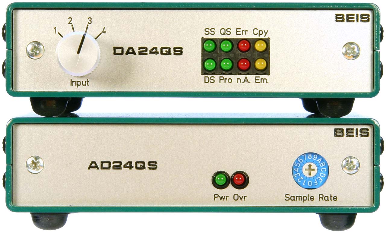
 8 LEDs on the front
indicate a couple of operational states:
8 LEDs on the front
indicate a couple of operational states:
Green: Sample Rate < 55.33 kHz (Single Speed, SSpd)
Green: Sample Rate > 55.33 kHz and < 110.67 kHz (Double Speed, DSpd)
Green: Sample Rate > 110.67 kHz (Quad Speed, QSpd)
Green: Professional Format (Pro)
Red: Receive Error or No Signal (Err)
Red: No Linear PCM Audio (i.e., the digital signal is a surround sound signal or something like that, NoAu)
Yellow: Copyright Asserted (Copy)
Yellow: Emphasis Signalled (Emph)
One of these LEDs should always be lit, so there is no Power-LED provided. The Double Speed LED is lit together with the red "Receive Error or No Signal" LED when there is no digital audio signal present because in this case the AD24QS generates its own digital "zero" audio signal at a rate of 96 kHz.
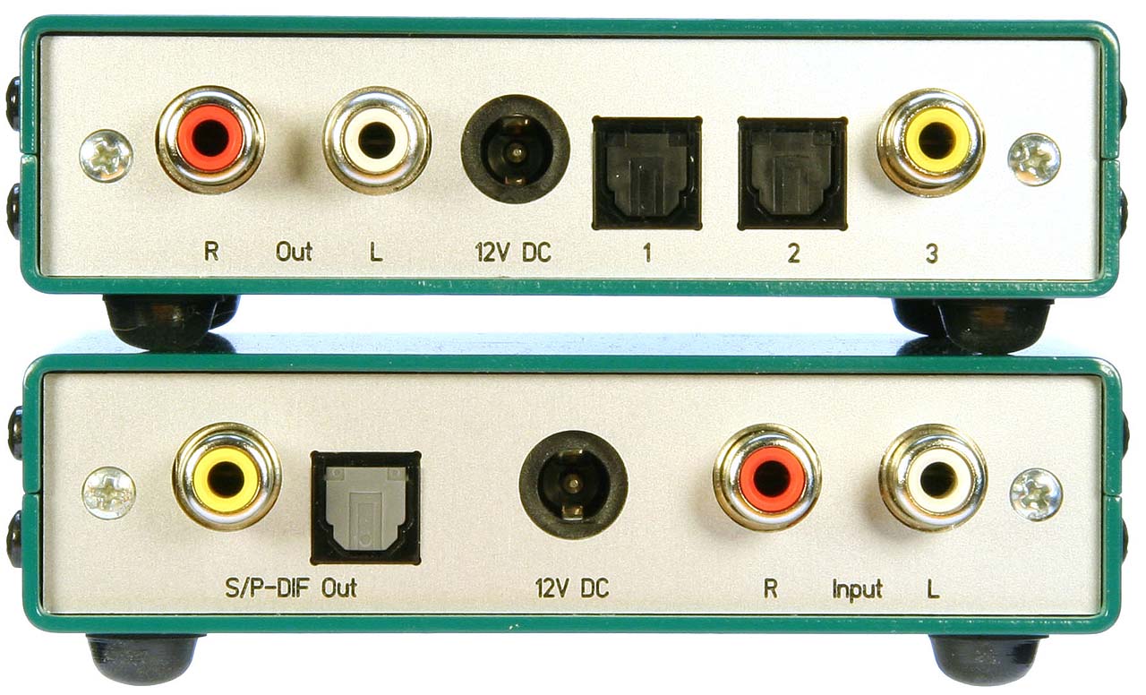
 All
connections are made on the rear. On-board there are 3 digital
audio inputs: Input 1 and 2 are optical (Toslink) ones and input
3 is an unbalanced, transformer-coupled Cinch input. A 4th
input, e.g. a balanced (XLR- or AES-3-) digital audio input with
its own digital audio transformer can be connected externally.
The inputs are selected with the input selector switch on the
front panel.
All
connections are made on the rear. On-board there are 3 digital
audio inputs: Input 1 and 2 are optical (Toslink) ones and input
3 is an unbalanced, transformer-coupled Cinch input. A 4th
input, e.g. a balanced (XLR- or AES-3-) digital audio input with
its own digital audio transformer can be connected externally.
The inputs are selected with the input selector switch on the
front panel.
The output level of the analog, unbalanced Cinch- (or RCA.) outputs is 2 VRMS approx, matching the output levels of usual CD or DVD-players. As options, balanced (XLR-) outputs can be connected. See the DIY section for details.
They need the extra balancing output amplifiers to be placed which are dimensioned for an output level of 12 dB headroom above the standard studio level of 4 dBu, i.e., 20 dBu = 4.96 VRMS for 100% FS in the circuit diagram.
The DA24QS provides unbalanced on-board Cinch audio outputs with 2 VRMS at 100% FS, a usual level e.g. for CD or DVD players. Also prepared are balanced outputs for XLR-jacks carrying output levels of 4.91 VRMS at 100% FS, which corresponds to +16 dBu or 12 dB above the standard studio level of +4 dBu (i.e, the headroom is 12 dB). On the photo you see the amplifiers and the Micro-Match connector for the balanced outputs populated, but the XLR-jacks are not connected.
The power supply is 12 V DC and the current consumption is from 200 mA (low sample rate, no audio signal) up to almost 300 mA (192 kHz, full scale sine wave signal), so the DA24QS gets warm.
Up to now, I did not measure any more technical data. I expect no surprises - the performance should be very close to the specified CS4398 performance, i.e., a typical dynamic range of 120 dB (A-weighted) and THD+N of -107 dB typically.
 For
the current circuit diagram of the DA24QS, have a look at either
the GIF-file
or the PDF-file.
For
the current circuit diagram of the DA24QS, have a look at either
the GIF-file
or the PDF-file.
I use a Cirrus Logic CS8416 "192 kHz Digital Audio Interface Receiver" in hardware mode. The hardware mode provides not quite enough functionality, i.e., signal outputs from control, for my goals. To overcome this I introduced a more complex control CPLD. Four digital audio inputs can be selected by the receiver's input multiplexer. On-board are two optical input devices (Toslink TORX147PL) as well as one unbalanced electrical output (0.5 VPP @ 75 Ω terminated) provided. Moreover, the DA24QS can be equipped externally with a professional digital audio input, either balanced (XLR, AES-3, 2 VPP @ 75 Ω terminated) or unbalanced (BNC, 1 VPP @ 75 Ω terminated). The decoupling transformer and the termination resistors are provided on board.
The optical input device (TOTX147PL) is specified up to slightly more than 96 kHz only, though it works on the workbench up to 192 kHz. Anyhow, I do not recommend to use it for 192 kHz.
The digital audio transformer for the coaxial signal is not specified for 192 kHz either, but when you have a look at its frequency response or its pulse transmission characteristics you understand why I unscrupulously use and recommend it. It would be fine for even much, much higher frequencies than 192 kHz.
The supply voltage for the receiver's PLL is regulated to 3.3 V by a precision TL431 shunt regulator. This was one of the lowest noise regulators I found, but I expect that noise does not matter much because the reference voltage noise is very well filtered by the receiver's external filter components, just like in the ADC's and DAC's reference supplies.
The CS4398 is Cirrus Logic's "Flagship" delta sigma D/A converter, specified with 120 dB dynamic range. The reference supply is a simple 78L05A, but there is no reason for concerns about its noise as reference voltage noise is very well filtered by the DAC's external filter components.
Unlike in the AD24QS the only analog stage is not designed fully balanced. This stage is a 2nd order low-pass Butterworth filter with a corner frequency of 100 kHz approx. and a differential input and a single ended output, supplying the unbalanced signal for the Cinch output jacks. In order to maintain the extreme high dynamic range I use an extra low-noise (and expensive) op-amp LM4562. Also, the filter network resistors must on one hand be as low as possible to generate as less noise as possible, but on the other hand they must not overload the DAC's output. Note, that the values of the filter's passive components are not symmetrical. This is because only by this way both outputs are loaded equally.
The DA24QS can be equipped with external professional, balanced audio outputs (XLR). For this purpose the additional balanced output op-amp stages (IC4.2 and IC5.2) needs to be populated along with the Micro-Match (or compatible) connector for the balanced outputs. On the photo you can see the position for the optional output stages and the Micro-Match connector, but it is not populated there.
The logic for the DA24QS is much more complex than the one for the AD24QS. Most important is the need for a sample rate detector. The DAC-IC (CS4398) must be supplied with an information whether it operates at single, double or quad speed. For this "frequency range detector" I chose an EPM3064, a CPLD in a 44-pin PLCC-package with 64 macrocells from Altera. This CPLD also takes up some more functions like extracting the "Professional", the "Copyright" and the "Emphasis" bits from the control data stream, controlling the emphasis function of the CS4398, generating a power-up reset signal and finally driving all 8 LEDs. The CPLD is not too expensive and in kits you'll get them programmed, of course.
Emphasis, by the way, does not work in quad speed mode, because the CS4398 is not capable of that. Emphasis in quad speed mode will be indicated, but not "executed".
There are a couple of components for the reset circuitry not populated. They were intended in case the CPLD provides a buffer for a reset generator only, but in the EPM3064 currently (just) enough macrocells for a 0.3 s reset timer are remaining, so these components are not needed.
One major issue I attached importance to is that the DA24QS does not produce noise when the S/P-DIF input signal is missing. In other concepts, like in the DA24QS's predecessor DA2496, without a digital input signal the S/P-DIF-PLLs tune to very low frequencies. Because DAC-ICs run at that frequency, too, the DAC's noise-shaped spectrum starts to rise at such low frequencies that a clearly audible amount of this noise shifts into the audible band. In the DA24QS, without an S/P-DIF input signal, the word clock is switched to slightly more than 96 kHz, derived by the S/P-DIF receiver IC from a 25 MHz crystal oscillator.
The nominal supply voltage for the device is 12 V, but up to 15 V are allowed and it operates down to 10 V or less. The power input is protected against polarity reversal and buffered with an extra large 1000 µF capacitor .
The digital part of the DA24QS operates at 3.3 V, only the analog output of the DAC-IC operates at 5 V. I provided a linear regulator, an LM317 in a TO220-package, to regulate the digital supply voltage. As the current consumption on the 3.3 V rail is quite high and the voltage drop is quite high, too, the LM317 gets quite hot, i.e., you can touch it for a few seconds only.
Like in the AD24QS, the negative analog supply voltage is generated by a DC-DC voltage inverter (LT1054, up to 15 V / 100 mA) and both the positive and the negative analog supply voltages are smoothed by one low-pass emitter follower each.
For different reasons I sell these converters as kits and thus for DIYs only.
With one exception, a TSSOP package, I'd say "No". I'll come later to this exception.
I expect sufficient experience from people to assemble the kits. I don't explain how to read resistor values, how to discriminate a 100 µH inductor from a 100 Ω resistor, which components are polarized, on which side the soldering iron gets hot and so on. The most difficult thing might be to solder the SO-IC packages, though I don't find this to be really difficult. You don't need much more than a fine solder tip, fine tin-solder and a steady hand. I try to avoid SMDs, but modern ICs are no longer available in DIL.
What even happens to me is that I mix up similar looking resistors, put components in the wrong places or rotate ICs by 180°. Usually all this soon becomes quite obvious and can easily be corrected.
The exception is:

 One
thing I would really like to have avoided is the use of an IC
with TSSOP package, but unfortunately the CS4398s are not available
in SOP like the other ICs. I don't have much problems soldering
it by hand because meanwhile I am experienced and I have appropriate
tools and resources. But an average DIY might come into trouble.
This is why I offer the kits with pre-soldered CS4398 (I'm not
going to do this by hand but in the reflow oven in my office).
One
thing I would really like to have avoided is the use of an IC
with TSSOP package, but unfortunately the CS4398s are not available
in SOP like the other ICs. I don't have much problems soldering
it by hand because meanwhile I am experienced and I have appropriate
tools and resources. But an average DIY might come into trouble.
This is why I offer the kits with pre-soldered CS4398 (I'm not
going to do this by hand but in the reflow oven in my office).
Have a look on the right photo and compare the sizes of an SOP and a TSSOP package. (Click in the photos for a high resolution picture.) The scale of both pictures is identical. Both ICs are hand soldered and afterwards carefully cleaned.
On the left you see my extra thin solder tip (actually a Weller 0.8 mm tip which became even finer with time) and the 0.5 mm tin solder. You should not dare to solder a TSSOP package without having solder removal wick, just in case.
The kits I provide come with all necessary electronic and mechanical parts for the basic version of the DAC, the DA24QS-K (no 4th digital audio input, no connector or op-amps for balanced analog outputs). The CPLD is programmed. The kits come without an enclosure, front or rear panel but with a 12 mm aluminium knob - just as you can see on the photos, except for the IC-sockets and the four stand-offs with their screws visible there.
See the BOM (bill of material) for what is actually included in the kit.
Find here the assembly drawings:

|
|
|
| Indicating the component names | Indicating the component types or values |

|
|
|
| Indicating the component names | Indicating the component types or values |
 Normally
all axial components, i.e., resistors, diodes and inductors, come
cut and bent. This saves a lot of assembly time for you and may
help that the assembly looks neater. Not all components on the
board need to be populated. They are partially intended for options.
Which one is to be populated and where is shown in the assembly
drawings.
Normally
all axial components, i.e., resistors, diodes and inductors, come
cut and bent. This saves a lot of assembly time for you and may
help that the assembly looks neater. Not all components on the
board need to be populated. They are partially intended for options.
Which one is to be populated and where is shown in the assembly
drawings.
4 jumpers, indicated red in the assembly drawing, must be placed at L1.1 and L2.2. For these slightly longer wires (5 mm) I prefer colored insulated ones because it looks better.
Balanced AES-3 Input: For the balanced digital audio input another digital audio transformer, a pin header and a few passive components are needed.
Balanced Outputs: I can offer a set of components including the op-amps, passive components, the Micro-Match connector and the appropriate ribbon cable.
EMC chokes: For an improved EMC (electro-magnetic compatibility) the board is prepared for two common mode chokes, L1 and L3. One is for the power supply input, the other one for the unbalanced, digital audio output. I pay attention to EMC performances but I am not able to test them. I prepared the chokes "just in case". Under normal circumstances they are not required.
Anyway, the DAC should always be installed into a well shielding enclosure!
I don't regard IC sockets to be necessary, but as I usually make experiments with my prototype devices, I use them there. This is why you see sockets on my photos, but they are not included in the kits.
 For
my units I used an SG206 enclosure from the (German) company
Fischer Elektronik. Front panel, enclosure
and board are directly fixed to each other using the element 5.60.422 from the (German) company
Ettinger,
available at Bürklin. You need not necessarily use
the enclosure I used. The board can easily be built into other
enclosures. For this enclosure I provided a detailed dimensional
drawing, either as a GIF
file or as a PDF
file. You will see there how the board is fixed within the
SG206 and how it can alternatively be fixed directly to other
front panels. Of course you may also use four stand-offs, distance
bolts or distance tubes to fix the board on the bottom of your
enclosure. The drilling positions can be found in the dimensional
drawing, too.
For
my units I used an SG206 enclosure from the (German) company
Fischer Elektronik. Front panel, enclosure
and board are directly fixed to each other using the element 5.60.422 from the (German) company
Ettinger,
available at Bürklin. You need not necessarily use
the enclosure I used. The board can easily be built into other
enclosures. For this enclosure I provided a detailed dimensional
drawing, either as a GIF
file or as a PDF
file. You will see there how the board is fixed within the
SG206 and how it can alternatively be fixed directly to other
front panels. Of course you may also use four stand-offs, distance
bolts or distance tubes to fix the board on the bottom of your
enclosure. The drilling positions can be found in the dimensional
drawing, too.
The front panel is manufactured by Schaeffer AG (in Europe) and is available in the US from Front Panel Express, LLC, too. You need the design files for the front and the rear panel, then you just have to send it to the manufacturer and you'll get a perfectly milled and engraved front panel, as the photos show. You may also modify the design file with the front panel design software "Front Panel Designer" German or English (it's free and very convenient) so that it fits to other enclosure of your choice.
All companies mentioned above have international branches, e.g. in the USA.
... is explained on page AD/DA24QS_Order.
| Last update: October 12th, 2015 | Questions? Suggestions? Email Me! | Uwe Beis |