| |
|
Analysis of the Goertzel algorithm
Explanation, additional information, but also a little criticism
(![]() Deutsche Version: Analyse des Goertzel-Algorithmus)
Deutsche Version: Analyse des Goertzel-Algorithmus)
| |
|
Analysis of the Goertzel algorithm
Explanation, additional information, but also a little criticism
(![]() Deutsche Version: Analyse des Goertzel-Algorithmus)
Deutsche Version: Analyse des Goertzel-Algorithmus)
Every now and then someone asks in a forum how to recognize a specific frequency in a digitized audio signal. The answer I often read is "Just use the Goertzel algorithm" - often enough with the undertone "Don't be so stupid!". I have only had an analog application like this so far, but not yet a digital one. I would have used a 2nd order digital IIR filter and parameterized it so that it would work like a 2-pole analog bandpass filter with a pronounced resonance.
But it seemed even easier with the Goertzel algorithm, and I didn't want to die stupid. What I found on the WWW during my brief search was not very enlightening. The authors obviously knew what they meant, but I, despite my knowledge of digital filters, did not. It was supposed to be a special form of FFT, or even DCT... Well, at some point, the enlightenment came from somewhere - and the surprise:
The Goertzel algorithm is almost the same as what I would have done with a digital IIR filter. And because of the differences, in practice I would rather use an IIR filter than the Goertzel algorithm. So the answer to the question could just as well (or even better) have been “Just use an IIR filter”. And it would be just as helpful.
Did Gerald Goertzel already know the theory of digital filters when he developed this algorithm in 1958?
I don't just want to explain the Goertzel algorithm here, but also compare it with the pure IIR filter and its analog counterpart. And, which is obviously not considered worth mentioning in the forums, also explain the parameterization and other effects of the filters that need to be considered. In the end, it turned out to be much more text than I had intended. Too much text? Maybe. But "Just use the Goertzel algorithm" is definitely too little text.
To do this, I write the Goertzel algorithm as a (not quite complete) Basic program:
    Dim Z1, Z2 As Double        'Two internal registers with a larger word width
    Dim X(BlockSize) as Integer 'Memory for a block with samples
    SR = SampleRate             'E.g. 48000 Hz
    FF = FilterFrequency        'E.g. a 1500 Hz ring tone
    N = BlockSize               'Number of samples that lead to a result
    Pi = 4 * Atn(1)             'Because Basic does not know Pi
    W = 2 * Pi * FF / SR        'Ratio FilterFrequency/SampleRate * 2Pi
    CW = Cos(W)                 'The cosine of W is closer to 1 for higher frequencies
    SW = Sin(W)                 'The sine of W is closer to 0 for higher frequencies
    Do                          'Continuous loop, calculate one block per run
        Z2 = 0                  'The two internal registers are set at the beginning
        Z1 = 0                  '    of the calculation of a block
        For J = 1 To N          'For all N samples of a block:
            Z2 = Z1             '"Shift register"
            Z1 = Z0
            'X(J) is the value of this sample:
            Z0 = X(J) + 2 * CW * Z1 - 1 * Z2 'New input value of the shift register
        Next J
        'Now a block has been calculated, the result Y can be output:
        Q = SW * Z1             'The real part of the result
        I = CW * Z1 - Z2        'The imaginary part of the result
        Y = Sqr(I ^ 2 + Q ^ 2)  'Y = Amount (length of the vector I,Q) is the result
    Loop
To explain what happens in this filter, I will take a detour via analog technology. Anyone with a little knowledge of resonant circuits will find this helpful, because what happens here is very similar to what happens with the digital algorithm. However, the Goertzel algorithm not only consists of a filter, but also contains an evaluation of the filter content, so that the spectral component of the filter frequency in the signal is produced as a measured value. This can, for example, either be displayed or compared with a threshold value for recognizing a tone (“ringing tone”).
I am writing about bandpass filters here, but we are actually talking about 2nd order lowpass filters with a pronounced resonance at the end of the band, i.e. 2nd order Chebycheff lowpass filters with very high ripple. As an analog circuit, such a low-pass filter can consist of capacitance C, inductance L and damping resistor R and looks as follows, for example:

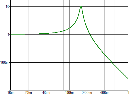
If R is small enough, there is a resonance at the frequency at which the impedances XL (of L) and XC (of C) are equal. R determines the quality of the resonant circuit. Example with R = XL/10 = XC/10 = 10:
R = 10 Ω
L = 100 H (XL = 100 Ω @ 159 mHz)
C = 10 mF (XC = 100 Ω @ 159 mHz)

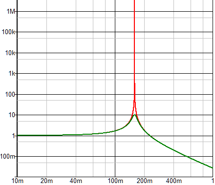
Low frequencies are passed 1:1, high frequencies are attenuated with 12 dB/octave, and at the resonance frequency the amplitude is 10 times higher, i.e. the quality factor Q is 10 (the quality Q must not be confused with the imaginary part Q in the above program). A normal digital filter can behave in exactly the same way, but the one in the Goertzel algorithm has a property that cannot be achieved with analog filters in reality: it has an infinitely high quality factor. In the analog counterpart, this would correspond to R = 0 Ω and L and C are ideal components. This can at least be simulated:

As is well known, in an oscillating circuit energy E always oscillates between two energy stores, in this case between the capacitance with the energy EC = 1 /2 · C · U² and the inductance with the energy EL = 1 /2 · L · I². The total energy is E = EC + EL. If an input signal precisely matches the filter frequency and is continuously present, a filter with infinitely high quality has the property that the amplitude of the current and voltage increases linearly over time and thus its energy content increases quadratically. This is precisely the case in the filter of the Goertzel algorithm. More on this shortly.
In order to measure the spectral component of its frequency in the signal with such a filter with extremely high quality, the filter would have to run for a defined period of time, then its energy content would have to be determined as the measured value, and the voltage and current in L and C would have to be set to 0 again for the next measurement. Although this would be possible for an analog solution, it would be quite nonsensical. It's easier digitally, and that's how the Goertzel algorithm works.
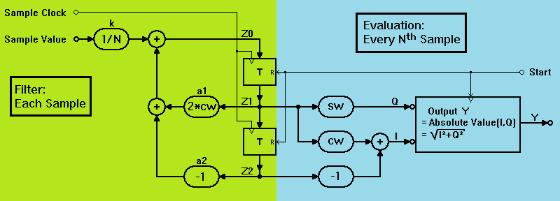
Let's take a look at the digital algorithm as a block diagram:

Brief overview:
The algorithm in the left green area is essentially a 2nd order digital filter in direct structure 2. It corresponds to the for-next loop in the code above as well as the ideal analog filter (i.e., R = 0 and L and C ideal) and is executed for each input sample. Analog to the ideal analog circuit, what corresponds to the amplitude and energy in its registers increases steadily in the resonance case. cw and sw stand for the cosine and sine of the ratio of sampling rate to filter frequency.
To evaluate the filter content, the algorithm in the right-hand blue area is used to determine the energy content achieved up to that point after a defined number of N samples. However, the output is not the energy I² + Q², but the square root of it, because the energy increases with the square of the amplitude in the registers, but a value proportional to the amplitude is desired, i.e. sqrt(I² + Q²).
There are a couple of important correlations in the digital filter, which you may not necessarily have to understand in order to use it, but you should be aware of some of them at the latest when implementing them so that you don't “fall flat on your face” due to ignorance.
It is easy to explain that this filter filters a certain frequency and that it has an infinite Q factor:
This characteristic of infinite quality is determined by the coefficient a2 = ‑1. With higher coefficients, e.g. ‑0.99, the register contents would not be able to become arbitrarily large. The filter would be attenuated and its amplitude response would be more, but not exactly like the bandpass filter with Q = 10 shown above (but the resonance frequency would also be different).
However, due to the limited number of samples, an infinite Q does not mean that only spectral components with exactly the theoretical filter frequency are detected. The limited number of samples has the same effect in practice as a filter with a finite Q factor. This means that spectral components close to the filter frequency are also included in the measurement, but with a correspondingly reduced amplitude.
If, as with the Goertzel algorithm, the coefficient a2 = ‑1, the coefficient a1 = 2·cw = 2 · cos(2 · Pi · FF / SR) determines the resonance or filter frequency. It is < 2, and the closer it is to 2, the lower the filter frequency becomes.
Example: A frequency of 1500 Hz at a sampling frequency of 48000 Hz is to be calculated. The result is: a1 = 2·cw = 2 · cos(2 · Pi · 1500 / 48000) = 1.96157056080646
By the way: Not only the filter frequency is determined by the coefficient a1, but also the DC gain G is changed: G = 0.5 / (1 ‑ cw). In the previous example, G = 0.5 / (1 ‑ cw) = 26.0217172299543, which means that all spectral components below the resonance frequency would appear in the register values amplified by at least a factor of 26. In practice, however, this is rather insignificant, because the lower the resonant frequency, the higher this influence is, but at the same time the energy content in the spectrum below the resonant frequency is also lower.
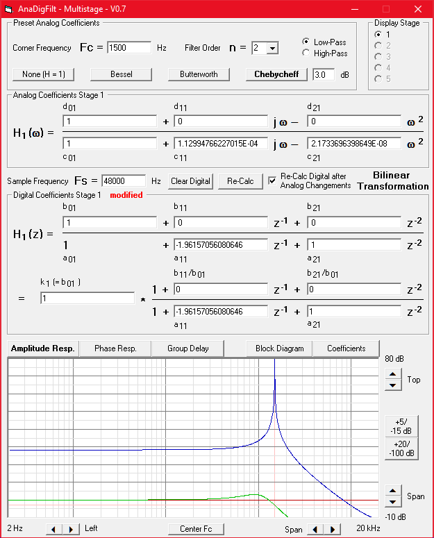
A long time ago I wrote the program AnaDigFilt, with which digital filters can be dimensioned from analog templates. It can also be used to display frequency responses of digital filters using given coefficients. This was very helpful when writing this article. It is (unfortunately) an EXE file for Windows that can be downloaded from the Converting Analog into Digital (IIR) Filters page. Note: To display the frequency response of the example, you must enter
In the header the analog coefficients:
Fc = 1500 Hz (only so that a line appears at 1.5 kHz)
Filter Order n = 2 (because it is a 2nd order filter)
The digital coefficients are not calculated from the analog ones, but inserted manually:
either the upper ones from the upper equation of this screenshot or the lower ones from the lower equation.
A suitable diagram section then needs to be set.

The resonant frequency of 1.5 kHz and the DC amplification factor of approx. 26 = approx. 28 dB are comprehensible.
With every digital filter there is a situation that I fear is easily overlooked if you don't know the background. This can have dire consequences: The input value, which has a certain word width or number of bits or resolution, should not be reduced unnecessarily in the following calculation. However, this can happen quickly with filters:
If this is not taken into account, the calculated value can be distorted to the point of being completely unusable.
Example: For a filter with an assumed filter frequency of 50 Hz and a sampling frequency of 48000 Hz as well as a desired quality Q = 100 (this corresponds to a bandwidth of 0.5 Hz), 100·48000/50 = 96000 samples (2 seconds) are required. This means that the values in the registers can be almost 100000 times the input signal, so that there are either more digits before the decimal point, or the input signal is multiplied by coefficients k = 1/96000 (sensibly divided by 2^17 = 131072, so that only one more shift operation is required), which requires a corresponding number of digits after the decimal point. In any case, an additional 17 bits are required for the calculation in this example.
If, in this case, samples were present at the input as 16-bit values (integers) and the following calculation was also only carried out with 16 bits, no meaningful output values would be produced, even with very small input values.
Another example: If the filter frequency is to be 50 Hz again, the coefficient a1 = 2·cw = 1.99995716332826. The denominator of the equation H(z) is then 1 ‑ 1.99995716332826 + 1 = 0.0000428366717399875. Rounding up the value of a1 to 1.99996 - which is almost the same - would result in a resonant frequency of approx. 48 Hz. Calculating with a 32-bit float here would be “very thin ice”.
Because the values in the registers can be a maximum of N times the input signal, it makes sense to divide the input samples or alternatively later the output signals by N in order to obtain the same range of values as the input signal. In addition, a correspondingly high resolution should be used, which can include a large number of digits, especially at low cut-off or resonance frequencies.
The energy or the equivalent of the energy present in a digital filter can be calculated from
The calculation of the real part Q = sw · z1 and imaginary part I = sw · z1 ‑ z2 is shown in the block diagram, resulting in the equivalent of the energy E = I²+Q². However, this value is only calculated once at the end of a measuring period of N samples and is then output as the measured value Y = sqrt(E). The maximum that can occur for Y over a measurement period corresponds to the spectral component contained in the signal with the resonance frequency, accumulated over the number of samples. Ideally, for an input signal with amplitude = 1, Y = 0.5 · N will occur after N samples.
The behavior of the Goertzel algorithm can be illustrated graphically. For sinusoidal input signals with an amplitude of 1, the values Z0 and the measured values Y achieved up to that point are shown for 3 different frequencies over 1200 samples:
After N = 1000 samples, the registers are cleared and the measurement process is restarted.
With the Goertzel algorithm, data is always calculated block by block, as with a DCT or FFT, and a result is delivered at the end of the block. This means that different measured values are output for short bursts, for example, depending on their respective temporal position in relation to the blocks. It is the same with a DCT or FFT.
The measured value output can only jump at regular intervals, similar to digital multimeters, and I don't like that. But unlike digital multimeters, they don't offer the advantage of higher resolution. In addition, the measured value output will constantly jump more or less if a frequency other than the exact resonance frequency is present.
That's why I like the behavior of an analog filter, as well as the behavior of a “normal” digital IIR filter with finite quality, more: With each sample, a value is created in the registers that I can use at any time and not only at longer intervals, e.g. when a threshold value is exceeded or for continuous, quasi-analog display. Disadvantage: Depending on the requirements or “perfection” of the continuous output, more or less additional computing effort is required:
Apart from the factor a2 in the signal path Z2, which is between 0 and -1 for a finite quality, the filter would be identical to the green range of the Goertzel algorithm. To evaluate whether a threshold has been exceeded, only one register value needs to be checked for exceeding a threshold value. For a continuous, quasi-analog display, the right-hand blue part of the Goertzel algorithm would be the mathematically perfect solution, but it would also be simpler with a rectifier (absolute value) and a simple low-pass filter connected downstream.
For comparison, I show the behavior of a “normal” digital IIR bandpass filter with finite Q = approx. 30. I did not calculate the parameters a1 = 1.8145, a2 = ‑0.987 and k = 0.173 exactly, but determined them experimentally with AnaDigFilt. However, so that the scaling matches the previous one, the amplitude of the excitation here is = 5.4. After approx. 11 oscillations (3.7 ms), the amplitudes in the registers reach approx. 70% of the final amplitude of approx. 1000.
Here, too, the filter will initially oscillate a little more strongly with a signal frequency that is slightly off, but will remain smaller in the long term. The ripple in the output Y (red line) is caused by the attenuation of the filter. In contrast to the ideal filter, this lossy filter loses some energy between the half-waves and regains it during each half-wave.
Tip: a2 = ‑0.987 does not necessarily have to be adhered precisely. a2 is decisive for the dampening or quality of the filter, which often does not have to be very accurate. If the hardware resources are scarce, you can save: With a2 = ‑1 + 1/128 + 1/256, i.e. with only two additional shift/add operations, a value for a2 of 0.9882813 is already achieved in this example, which is often sufficient in practice. With a further shift/add operation a2 = ‑1 + 1/128 + 1/256 + 1/1024 = 0.9873047, there is practically no difference in the behavior of the filter.
I certainly don't need to explain the DTMF dialing method here. In practice, the Goertzel algorithm is probably the most frequently used method for recognizing DTMF tones. However, a DTMF decoder does not only consist of 8 decoders for the 8 tones. They must be checked: Signal duration and signal strength as well as the twist or reverse twist must be within the tolerance range so that a tone pair can be recognized as valid or invalid. Finally, a valid pair of tones must activate one of 16 outputs.
If the full signal strength is to be detected in one measurement period, the measurement period according to the specifications should be no longer than 20 ms. On the other hand, it should also be possible to evaluate the sum of the signal strengths of two consecutive 40 ms measurement periods. This would lead to a smaller filter width, but also to slower reactions and would also require longer pauses between two identical tones. Two separate signal tones should actually be recognized even with pauses in the signal of more than 10 ms. This would only be possible with significantly shorter measuring times and correspondingly larger filter bandwidths.
But I don't want to discuss all this in detail here or even present a complete solution. I just want to suggest that "Use the Goertzel algorithm" is only part of the solution for a DTMF decoder. This article is only intended to help you determine the parameters for the filters of a DTMF decoder. Here is an advantage of a filter with infinite quality: Only one filter parameter, which depends on the sampling and filter frequency, is responsible for the filter frequency:
a1 = 2 · cos(2 · Pi · FF / SR)
In addition for evaluation:
cw = a1 / 2
sw = sin(2 · Pi · FF / SR)
For an IIR filter with limited quality, the parameter a2 would also have to be calculated. This is more complex because both parameters, a1 and a2, are dependent on the Q factor and the sampling and filter frequency. But I don't have any formulas to calculate this. Nevertheless, I would probably use this approach for a DTMF decoder.
| Last update: January 11th, 2025 | Questions? Suggestions? Email Me! | Uwe Beis |