| |
|
(Another) P48 to T12 Adapter
-with XLR input and output -
![]() (German Version: (Noch ein) P48-zu-T12-Adapter)
(German Version: (Noch ein) P48-zu-T12-Adapter)
| |
|
(Another) P48 to T12 Adapter
-with XLR input and output -
![]() (German Version: (Noch ein) P48-zu-T12-Adapter)
(German Version: (Noch ein) P48-zu-T12-Adapter)
I have a very nice HF condenser microphone with XLR connector, but unfortunately it requires 12 V phantom power (T12). Adapters and circuit diagrams for adapters that allow such older T12 microphones to operate on 48 V phantom power (P48) microphone inputs are many. Here is another one where the circuit differs only in one detail from the usual circuit, but I am concerned here with a construction of the adapter in a handy and readily available XLR housing.
The circuit differs from the frequently found variant only in that there are two double diodes. With these diodes possible overvoltages at the T12 microphone should be made harmless. These overvoltages might occur when plugging the P48 side and could endanger a T12 microphone connected at the same time.
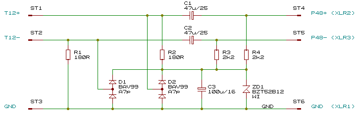
The dimensioning of the resistors is also as usual: With two 2.2 kΩ resistors connected in series to the two standardized 6.8 kΩ resistors of the P48 source and a 12 V zener diode, the result is a zener current of (48-12 V)/((6.8+2.2 kΩ)/2) = 36 V/4.5 kΩ = 8 mA, which is also the maximum supply current of the microphone.
The capacitors are chosen to provide as much capacitance as possible, but at the same time all three of them fit side by side in the intended package, which has an inner diameter of just under 16 mm. In addition, they must not be too high.
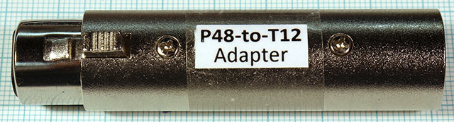
There are inexpensive small XLR adapter housings that suggest themselves to build such an adapter in there. But it's not that easy: The space for such an additional circuit is not exactly lush. Connecting pins have to be bent in a complicated way and the solder connections of the XLR socket and the plug have to be shortened.
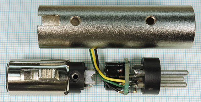
In the end, the adapter looks like this:
Inside, the housing has 2 x 3 ribs, 3 are on the socket side, 3 more are at other locations on the plug side:
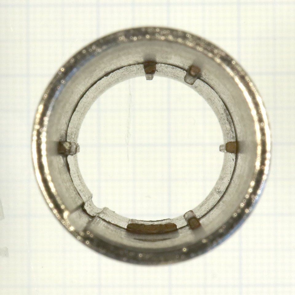
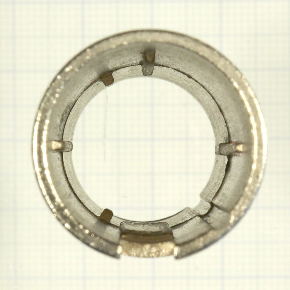
Connector side Socket side
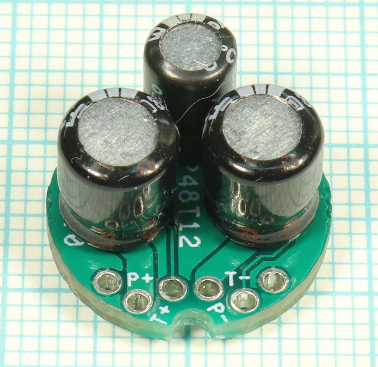
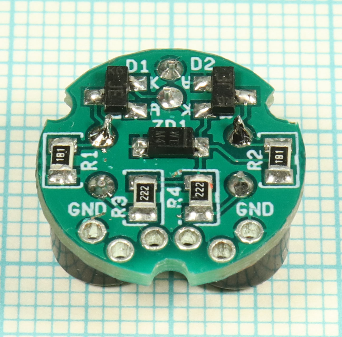
The assembled printed circuit board
Pins from 2.54 mm pin headers are soldered to the trimmed(!) connector pins and bent so that the PCB is arranged in exactly the right position in the housing. It is not easy, but necessary to bend them exactly to fit. It is the most challenging part of building this adapter.
Note: In case the printing P and T is confusing: 6 connections can be seen on the left photo, from left to right: ground, P+, T+, P-, T-, ground. P+, P- and ground go to the connector.


View of the bent pins already soldered to connector
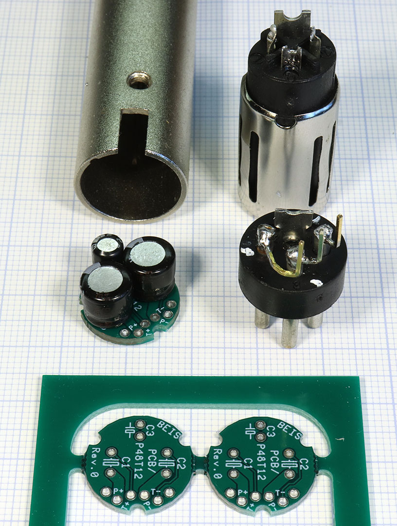
Once the pins have been soldered and bent successfully and the soldered PCB fits well into the housing, the socket is connected to the PCB with short stranded wires. The strands should be as short as possible, but also as long as necessary, so that they can be soldered to the trimmed(!) connections of the socket before assembly.
Ready for installation. The positions on the photo of plug and socket to each other also correspond to their final position in the housing.
| Anzahl | Bauteil | Quelle |
|---|---|---|
| 1 | Printed circuit board, PCB/P48T12 | Beis.de |
| 2 | Resistor, 180 Ω, size 0805 | Various |
| 2 | Resistor, 2.2 kΩ, size 0805 | Various |
| 2 | E-Cap, 47 µF, 25 V, D <= 7 mm, H <= 8 mm, RM 2,5 | E.g. Mouser ECE-A1EKA470I |
| 1 | E-Cap, 100 µF, 16 V, D <= 5 mm, H <= 8 mm, RM 2 | E.g. Mouser 80‑ESS107M016AC2KA |
| 1 | Z-Diode, 12 V, Bauform SOD123, z.B. BZT52B12‑E3‑08 | E.g. Mouser 78‑BZT52B12‑E3‑08 |
| 2 | Dual diodes, series connection, size SOT23, z.B. BAV99 | E.g. Mouser 771‑BAV99235 |
| 1 | XLR/XLR male/female adapter housing | E.g. Ebay |
| Stranded wires, pins from pin headers |
If you are interested in rebuilding this adapter: I still have a few sets of components left from the development, please ask if necessary. However, I have not yet thought about a price.
| Last update: October 11th, 2021 | Questions? Suggestions? Mail Me! | Uwe Beis |