| |
|
The CORDIC Algorithm
The "normal way" and the solution without multiplier to understand
(![]() Deutsche Version: Der CORDIC-Algorithmus)
Deutsche Version: Der CORDIC-Algorithmus)
| |
|
The CORDIC Algorithm
The "normal way" and the solution without multiplier to understand
(![]() Deutsche Version: Der CORDIC-Algorithmus)
Deutsche Version: Der CORDIC-Algorithmus)
Practically nobody needs the CORDIC algorithm anymore. In all high-level languages, all computers and all smartphones, the sine and cosine function is available as a ready-made function as a matter of course. For many, many years. Who still wants to struggle with it?
Ok, I have done it. Twice, in fact. In my DASG (Digital Audio Sine Wave Generator) I realized it almost 10 years ago in an FPGA with VHDL. And because I had simply forgotten how to do it in the meantime (which annoyed me), I wanted to know again. That's the only reason why I looked into it again, otherwise I wouldn't have an application. Well, the fact that an article came out of it was worth something after all.
I don't even know if I realized it at the time: there are two ways of calculating sine and cosine values:
In principle, this article is superfluous. Everything is shown more than completely in Wikipedia. However, it took me a very long time to understand at least the most important points of the very scientific article. I don't want to go into the criticism of comprehensibility any further here, but I still recommend the Wikipedia article because it also contains interesting historical aspects, among other things.
So I had resolved to do better in terms of comprehensibility and comprehensibility. After I thought I understood the algorithms, I tried it out in Visual Basic to see if I really got it. And when I did, the "supreme discipline": to implement the Arctan table based version in assembler on a µC that has no hardware multiplier. Finally, I will summarize my experiences in this hopefully comprehensible article.
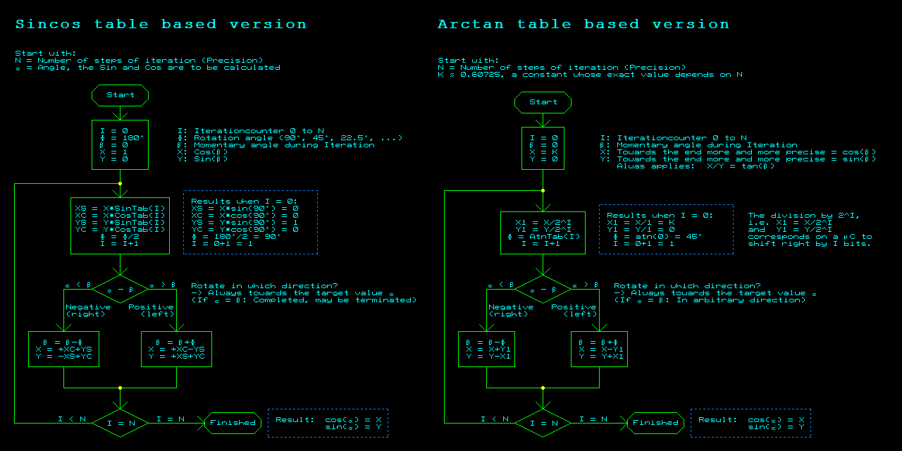
The CORDIC algorithm is used to iteratively calculate the corresponding sine and cosine values for a given angle α (alpha). I will try 1. to describe this in words, 2. to illustrate it with a graphic and 3. to describe the exact calculation algorithm with a flow diagram.
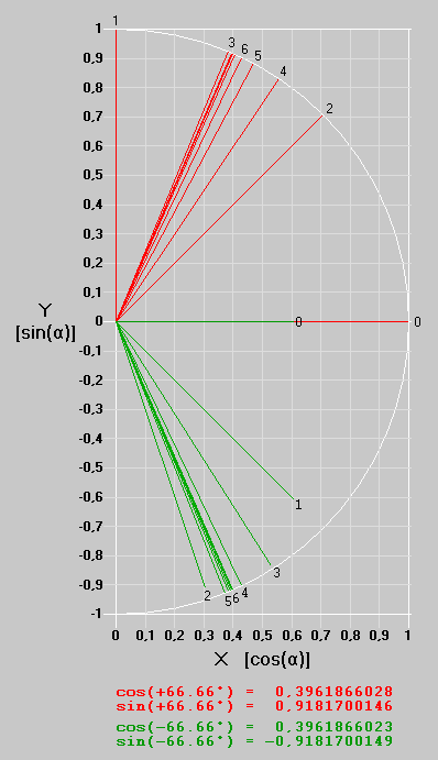
In the Sincos table-based version, this is shown in the following graphic with the red vectors for α = +66.66° and works as follows:
It makes sense to repeat this loop 4 to 6 until the rotation angles Φ are so small that the accuracy does not increase any further because numbers are only calculated with finite resolution. The cosine and sine values of the rotation angles Φ are required for the coordinate rotation. These must be available in advance in a sine and cosine table. Multiplications and additions or subtractions are also carried out.
So much for an attempt to provide a rough overview of this CORDIC algorithm in words. The example in the following graphic may make it easier to understand. In the upper half, the vectors of the iteration steps for the Sincos table based version are shown in red with the start value (X, Y) = (1 ,0) and the angles β for the target α = +66.66°, whereby the start value and the first 6 iteration steps are numbered 0 to 6:

The Arctan table based version is not completely different, but there are clear differences. This is shown in green for the target α = -66.66° in the lower half of the graph:
I have created the two algorithms in detail with a less suitable, but not completely unsuitable program:

The sine and cosine tables are calculated from:
SinTab(I) = sin(90°/2^I)
CosTab(I) = cos(90°/2^I)
with I = 0 up to the number of iteration steps N - 1 (= N table entries).
The arctangent table is calculated from:
AtnTab(I) = atn(1/2^I)
with I = 0 up to the number of iteration steps N - 1 (= N table entries).
The arctangent table for 32 iteration steps then looks like this:
I AtnTab(I)
0 0,78539816339745
1 0,46364760900081
2 0,24497866312686
3 0,12435499454676
4 0,06241880999596
5 0,03123983343027
6 0,01562372862048
7 0,00781234106010
8 0,00390623013197
9 0,00195312251648
10 0,00097656218956
11 0,00048828121119
12 0,00024414062015
13 0,00012207031189
14 0,00006103515617
15 0,00003051757812
16 0,00001525878906
17 0,00000762939453
18 0,00000381469727
19 0,00000190734863
20 0,00000095367432
21 0,00000047683716
22 0,00000023841858
23 0,00000011920929
24 0,00000005960464
25 0,00000002980232
26 0,00000001490116
27 0,00000000745058
28 0,00000000372529
29 0,00000000186265
30 0,00000000093132
31 0,00000000046566
The factor K corrects the change in length of the vector over the course of the iteration. K is the reciprocal of the product of all cos(Φ) from 0 to the last iteration step applied. For N > 24, K = 0.607252935008881 or hexadecimal with a value range of 0 to 2^32 corresponding to 0 to 1, K = 0x9B74EDA8.
For the 32-bit algorithm in a µC or in other binary computing platforms, the AtnTab(I) would look like this:
.long 0x20000000 ; Φ = atn(2^ 0) = 45°
.long 0x12E4051E ; Φ = atn(2^-1) = 26,565051177078°
.long 0x09FB385B ; Φ = atn(2^-2) = 14,0362434679265°
.long 0x051111D4 ; Φ = atn(2^-3) = 7,1250163489018°
.long 0x028B0D43 ; Φ = atn(2^-4) = 3,57633437499735°
.long 0x0145D7E1 ; Φ = atn(2^-5) = 1,78991060824607°
.long 0x00A2F61E ; Φ = atn(2^-6) = 0,895173710211074°
.long 0x00517C55 ; Φ = atn(2^-7) = 0,447614170860553°
.long 0x0028BE53 ; Φ = atn(2^-8) = 0,223810500368538°
.long 0x00145F2F ; Φ = atn(2^-9) = 0,111905677066207°
.long 0x000A2F98 ; Φ = atn(2^-10) = 5,59528918938037E-02°
.long 0x000517CC ; Φ = atn(2^-11) = 2,79764526170037E-02°
.long 0x00028BE6 ; Φ = atn(2^-12) = 0,013988227142265°
.long 0x000145F3 ; Φ = atn(2^-13) = 6,99411367535292E-03°
.long 0x0000A2FA ; Φ = atn(2^-14) = 3,49705685070401E-03°
.long 0x0000517D ; Φ = atn(2^-15) = 1,74852842698045E-03°
.long 0x000028BE ; Φ = atn(2^-16) = 8,7426421369378E-04°
.long 0x0000145F ; Φ = atn(2^-17) = 4,37132106872335E-04°
.long 0x00000A30 ; Φ = atn(2^-18) = 2,18566053439348E-04°
.long 0x00000518 ; Φ = atn(2^-19) = 1,09283026720071E-04°
.long 0x0000028C ; Φ = atn(2^-20) = 5,46415133600854E-05°
.long 0x00000146 ; Φ = atn(2^-21) = 2,73207566800489E-05°
.long 0x000000A3 ; Φ = atn(2^-22) = 1,36603783400252E-05°
.long 0x00000051 ; Φ = atn(2^-23) = 6,83018917001272E-06°
.long 0x00000029 ; Φ = atn(2^-24) = 3,41509458500637E-06°
.long 0x00000014 ; Φ = atn(2^-25) = 1,70754729250319E-06°
.long 0x0000000A ; Φ = atn(2^-26) = 8,53773646251594E-07°
.long 0x00000005 ; Φ = atn(2^-27) = 4,26886823125797E-07°
.long 0x00000003 ; Φ = atn(2^-28) = 2,13443411562898E-07°
.long 0x00000001 ; Φ = atn(2^-29) = 1,06721705781449E-07°
.long 0x00000001 ; Φ = atn(2^-30) = 5,33608528907246E-08°
.long 0x00000000 ; Φ = atn(2^-31) = 2,66804264453623E-08°
It can be seen that the last iteration step with I = 31 would no longer make sense, as the rotation angle Φ is 0. In principle, the same also applies to a calculation with 16-bit or 8-bit numbers for the last step, i.e. for I = 15 or I = 7.
With fewer iteration steps or low resolution, e.g. with 16 iterations and 16-bit calculation accuracy, only the first 16 bits of both the table and K need to be used, sensibly rounded.
It is obvious that the accuracy of the results depends on the resolution (number of digits) used for the calculation and the number of iteration steps. As rounding errors accumulate with each iteration, it must be expected that the last digit will be incorrect by several counters. In an experiment with 32-bit numbers and 32 iteration steps, I observed deviations of a maximum of +/-6 (out of two billion!) in the calculated sine and cosine values for approx. 30 different angles. I find this plausible.
It is advisable to use the same number of bits or digits for the input value α as for the tables, the intermediate registers and the output values.
The entire 16- or 32-bit numerical range for 0 to 360° is of course used as the angle input. In other words: 360° = 0xFFFF+1.
The output is a little "awkward": It is usual to understand the number range from 0 to 65535 with a sign as -32768 (0x8000) to +32767 (0x7FFF) with e.g. 16 bits. 0x8000 scaled as -1 for the sine calculation would be ok, but +1 would then not be displayable. It would be conceivable to scale 0x8001 to 0x7FFF as -1 to +1.
In my implementation, I have scaled 0x4000 as +1 and 0xC000 as -1. The number range 0x4001 to 0xBFFF then remains unused. So 1 bit sign, one bit before the decimal point, 14 bits after the decimal point. This also means that you do not have to start with K = 0x9B74EDA8, but with a quarter of it, i.e. K = 0x26DD3B6A.
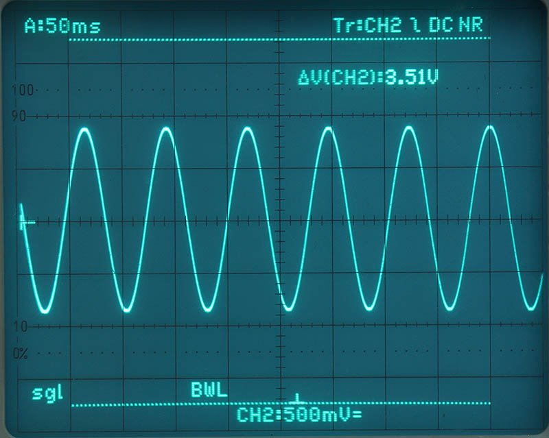
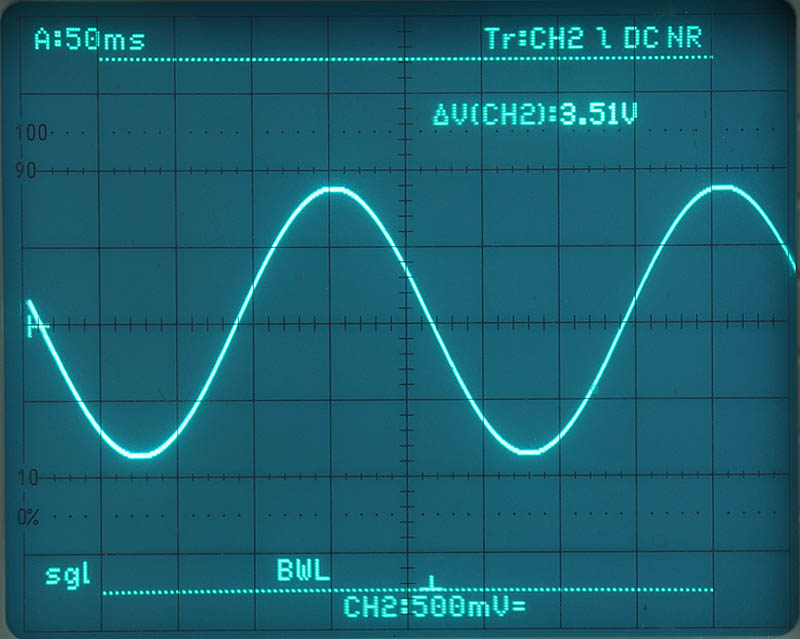
Of course, I didn't just want to try all this out with simulations. A meaningful demonstration should also run with a µC with the Arctan table based version, i.e. without a multiplier. The µC is an MSP430Gxxxx, a 16 bit µC from TI. A sinusoidal signal was to be generated and its MSByte converted to analog using the R2R network and displayed on the oscilloscope. And I wanted to find out what the calculation times were for the 16-bit and 32-bit variants. Result: At 16 MHz processor clock, a calculation takes
- with 16 bits approx. 63 µs
- with 32 bits approx. 220 µs
Most of the time is needed for the shift instructions. In the 32 bit version there are approx. 500 of these, each of which requires 7 processor cycles in a loop with loop counter and jump, which results in approx. 500*7/16 MHz = 220 µs. A barrel shifter would be very helpful, but this is not available in the MSP430. At least you can take shortcuts, because shift operations greater than 8 or 16 can be partially replaced by byte or word swapping and deletion, so a total time of approx. 220 µs can be achieved. With 63 µs for a 16-bit calculation, even sinusoidal signals up to several kHz are possible in real time, e.g. for frequency modulation.
For the demonstration, I have set the step size for each sample to 0x0055 (16-bit version) or 0x00550055 (32-bit version). A 360° cycle therefore requires ~771.011 calculations and thus takes a correspondingly long time. To avoid re-quantizing a digital scope for screenshots, I took photos with long exposures from the analog scope. First the 16 bit version, then the 32 bit version. The cursor lines show the operating voltage range, of which only about 50% is utilized due to the +1 problem mentioned above.


I am not publishing the code for the MSP430 here. Not because it is secret, but because it is not well maintained. But in this case, "The main thing is that it works" was enough for me for once. Otherwise, I consider this saying to be an admission of the lowest claim a developer can make of himself and his work, which is a great indictment. But for the estimated 0 people who would be interested in it, I didn't want to make the effort, and I don't need it anymore myself. However, if anyone is interested and is not afraid of anything - let me know.
| Last update: September 4th, 2024 | Questions? Suggestions? Email Me! | Uwe Beis |