| |
|
AD2-QC Kit
Assembly instructions and additional information
(![]() German Version: Bausatz AD2-QC)
German Version: Bausatz AD2-QC)
| |
|
AD2-QC Kit
Assembly instructions and additional information
(![]() German Version: Bausatz AD2-QC)
German Version: Bausatz AD2-QC)
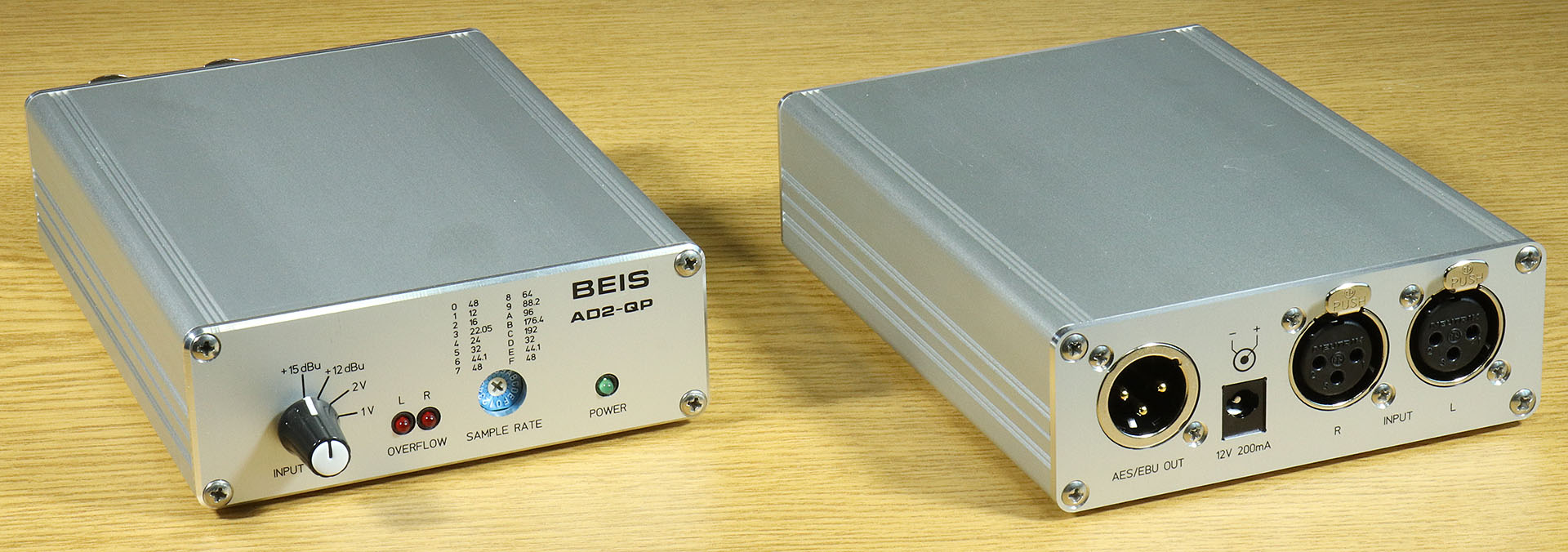
The AD2-QC kit (analog/digital converter, 2 channels, quad speed) is equipped with RCA inputs and outputs as well as an optical output for normal use. A modification of the AD2-QC is the AD2-QP, which is intended more for professional use and is equipped exclusively with XLR connectors for the inputs and the output. Both are functionally identical.
The kit is supplied complete with all the necessary components. The circuit board is equipped with all SMDs and tested on a special test station. A housing with front and rear panel is currently planned, but there is no sample yet.
I attach great importance not only to the technical properties of my developments, but also to a good appearance. With this in mind, I have also made a few comments in this description as to when and where, if I were to produce such a kit or a device myself, I would also make its "inner workings" visually appealing with a little more effort.
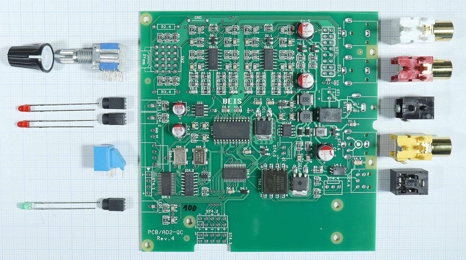
The photo shows all parts of the ADC2-QC kit except for the housing.
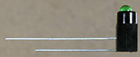 The LEDs for the operating voltage indicator (green) and overload indicator (2 x red):
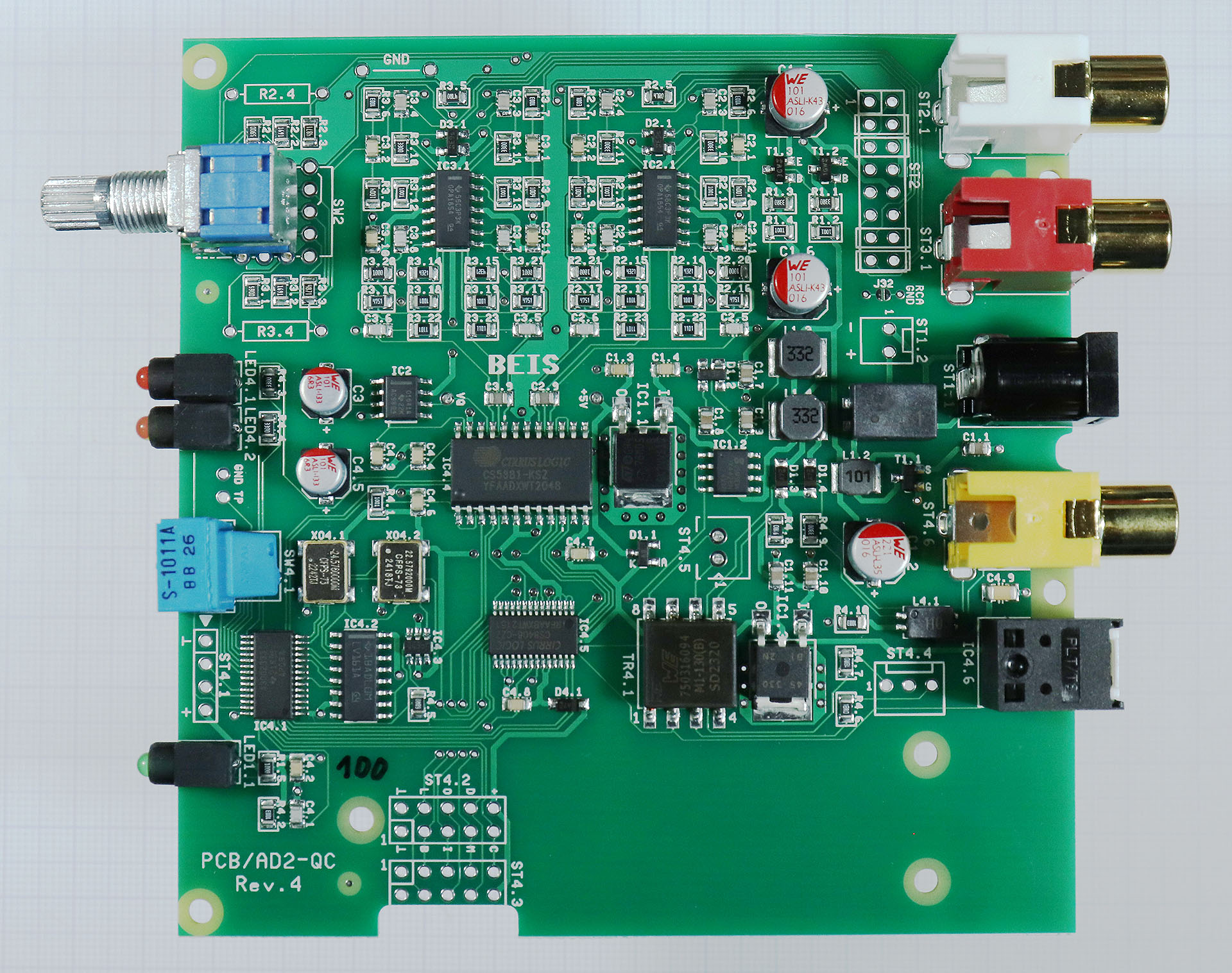
The AD2-QC is now basically ready for operation and can be tested.
The housing will look similar to the housing of the AD2-QP shown in the following photo, but is approx. 40 mm shorter and only 30 mm high. The back of course looks completely different.
The assembly of the housing should be self-explanatory, but I would like to give a few hints:
Two mounting blocks ("mounting brackets") are screwed to the back of the circuit board with one M2.5x6 mm pan-head screw each, not yet fully tightened.
The lower housing shell is screwed to the back plate with 2 M3x10 mm pan-head screws.
The module is inserted into the lower rail of the lower housing shell and fastened to the back plate with 2 M2.5x6 mm pan-head screws via the mounting blocks. The other two screws under the PCB can now also be tightened.
The front panel is fitted and also screwed to the lower housing shell using 2 M3x10 mm countersunk head screws. Attention: Make sure that the 3 LED holders protrude into the openings provided before screwing them in!
The upper housing shell can be fitted and screwed in place with 4 M3x10 mm pan-head screws.
Finally, 4 housing feet should be glued under the housing if necessary.
A simple function test should suffice as a final test. Some further information can be found in the article AD2-QC.
The following settings can be made with the SAMPLE RATE switch:
| Setting | Sample Rate (kHz) |
Format | ||
| 0 | 48 | Professional | ||
| 1 | 12 | Professional | ||
| 2 | 16 | Professional | ||
| 3 | 22.05 | Professional | ||
| 4 | 24 | Professional | ||
| 5 | 32 | Professional | ||
| 6 | 44,1 | Professional | ||
| 7 | 48 | Professional | ||
| 8 | 64 | Professional | ||
| 9 | 88.2 | Professional | ||
| A | 96 | Professional | ||
| B | 176.4 | Professional | ||
| C | 192 | Professional | ||
| D | 32 | Consumer | ||
| E | 44.1 | Consumer | ||
| F | 48 | Consumer |
The 12 sample rates, whose digital audio signal is referred to as "Professional Format", are selected in position 0 - C. Position 0 corresponds to the situation where the sample rate switch is not fitted. The sample rate is then set to 48 kHz.
Positions D, E and F are referred to as "consumer format", in which only 32 kHz, 44.1 kHz and 48 kHz can be selected. In consumer mode, the category code of the ADC is "General" (00hex) and copyright is not claimed.
With the INPUT LEVEL switch the input level UIN for 100% FS ("Full Scale") can be set to 4 levels:
For the +15 dBu switch position, the input level UIN for 100% FS can be set to a value between approx. 100 mVrms and +15 dBu. Two additional THT resistors RGain can be inserted in the slots provided for this purpose:
2 * UIN
RGain = ------------ kΩ
4.36V - UIN
The front panel label +15 dBu is then of course no longer correct. In principle, settings for even lower input levels than 100 mVrms (i.e. approx. 47 Ω) also work, but this is not recommended.
The 16-pin pin header ST2 provides everything you need to switch between the RCA inputs on the board and external inputs, e.g. balanced XLR inputs.
Furthermore, switches or potentiometers (preferably neg. logarithmic) can be connected via ST2 to set the gain or the 100% FS input level. The 4-stage switch "Input Level" (SW2) is then not installed or set to +15 dBu.
The input level UIN results from the variable resistance and a fixed series resistor of 47 Ω as follows:
4.36 * (RGain + 0.047kΩ)
UIN = ------------------------ V
2.047kΩ + RGain
With RGain in kΩ. The minimum achievable input level with RGain = 0 is therefore approx. 100 mV.
A balanced supply voltage is also available on ST2, e.g. for microphone preamps or RIAA equalizers.
An XLR connection for an AES3 or AES/EBU output can be connected via ST4.4 and also operated simultaneously with the S/PDIF and Toslink output.
A USB interface is planned as a plug-on module for the AD2-QC, but is not yet available. The area for the interface attached to the circuit board with 3 spacer pins and the position of the pin header for the connections between the interface and ADC can be seen in the photos. The functions of the interface and the behavior correspond to those of the DA2USB. To avoid ground loops (or other interference due to equalizing currents), the USB connection is galvanically isolated from the ADC ground.
The measured values for the audio signals practically correspond to those of the AD24QS, as is to be expected due to the similar technology.
| Sampling rates | 12 different ones, 12 - 192 kHz | |
| Analog inputs | RCA, unbalanced, 180 kΩ | |
| Input sensitivity at 100% FS |
Switchable 1 Vrms | 2 Vrms | +12 dBu | +15 dBu Other gains for the setting +15 dBu are possible with resistors that can be retrofitted |
|
| Dynamic range |
117 dB A-weighted (typical) |
|
| THD | t. b. d. (AD24QS: typ. -120 dB @ -6 dB FS) | |
| Common Mode Rejection Ratio (CMRR) | > 60 dB, typ. 70 - 80 dB, range ±8 V | |
| Power Supply Rejection Ratio (PSRR) | ca. 100 dB bei 100 Hz | |
| Frequency response @ +0 / -3 dB | SR 12 kHz up to 96 kHz: 2 Hz - SR/2 SR 192 kHz: 2 Hz - 78 kHz |
|
| Digital audio outputs | S/PDIF (RCA), coaxial 75 Ω and optical (Toslink) | |
| Latency | 192 kHz: 46 µs 96 kHz: 126 µs 48 kHz: 310 µs 44.1 kHz: 275 µs |
|
| Power supply | 12 V DC (10 - 15 V), typ. approx. 100 mA, max. < 200 mA Protected against reverse polarity 2.1 / 5.5 mm hollow plug, lockable |
|
| Dimensions (L x W x H) | 99 mm x 100 mm (PCB only) 105 mm x 105 mm x 30 mm (Housing only) |
|
| Weight | t. b. d. |
The measured values listed above are from a sample device and cannot be guaranteed.
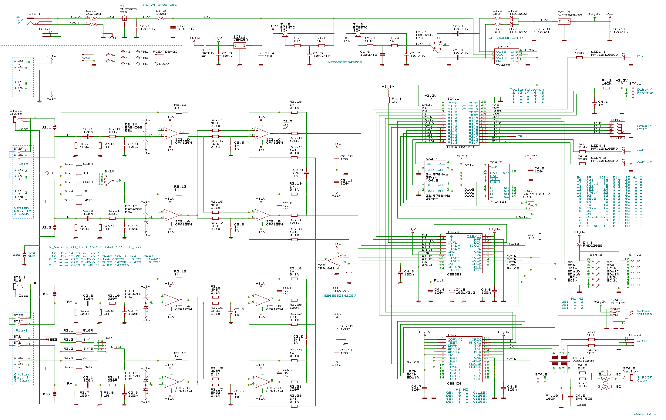
Finally here: The circuit diagram of the AD2-QC.
| Qty. | Part | |
| 1 | AD2-QC with SMDs | |
| 1 | Power jack 4840.2202 | |
| 1 | RCA white | |
| 1 | RCA red | |
| 1 | RCA yellow | |
| 1 | Opt. Transmitter PLT133 | |
| 1 | Switch SRBM/S1010 | |
| 1 | Knob | |
| 1 | LED WP710A10SGD | |
| 2 | LED WP710A10SRD/J4 | |
| 3 | LED Holder | |
| 1 | Hex Switch S1011A |
| Qty. | Part | |
| 2 | Profile GB48 | |
| 1 | Front Panel | |
| 1 | Rear Panel | |
| 8 | M3x10 A2 DIN966 (raised countersunk head) | |
| 2 | Threaded Block 15x5x5 | |
| 2 | M2,5x6 A2 DIN966 (raised countersunk head) | |
| 2 | M2,5x6 DIN7985 (tallow-drop screw) | |
| 4 | Bumpon SJ5302 |
The AD2-QC will soon be available as a kit with or without housing and as a finished device (probably with USB interface) from Heroms GmbH.
| Last update: November 24th, 2025 | Questions? Suggestions? Email Me! | Uwe Beis |