| |
|
AD2-QP Kit
Assembly instructions and additional information
(![]() German Version: Bausatz AD2-QP)
German Version: Bausatz AD2-QP)
| |
|
AD2-QP Kit
Assembly instructions and additional information
(![]() German Version: Bausatz AD2-QP)
German Version: Bausatz AD2-QP)
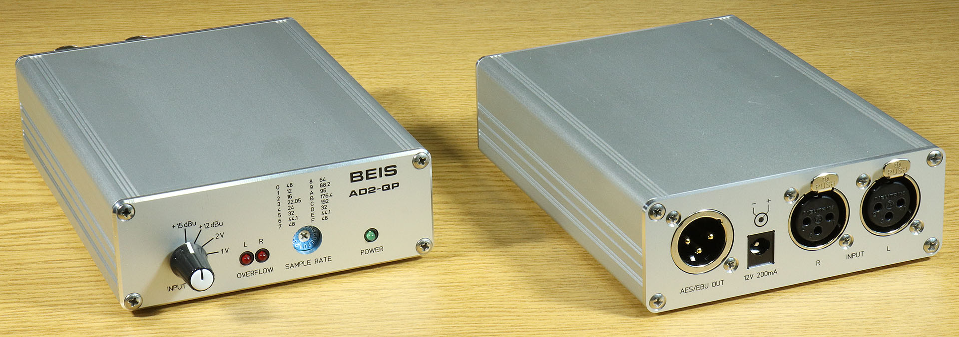
The AD2-QP kit (analog/digital converter, 2 channels, quad speed for professional use) with its XLR connections instead of the RCA inputs and outputs and the optical output is a modification of the AD2-QC, which is intended more for normal use. Both are functionally identical.
The kit is supplied complete with all the necessary components, either including or excluding the housing. The circuit board is equipped with all SMDs and tested on a special test station.
I attach great importance not only to the technical properties of my developments, but also to a good appearance. With this in mind, I have also made a few comments in this description as to when and where, if I were to produce such a kit or a device myself, I would also make its "inner workings" visually appealing with a little more effort.
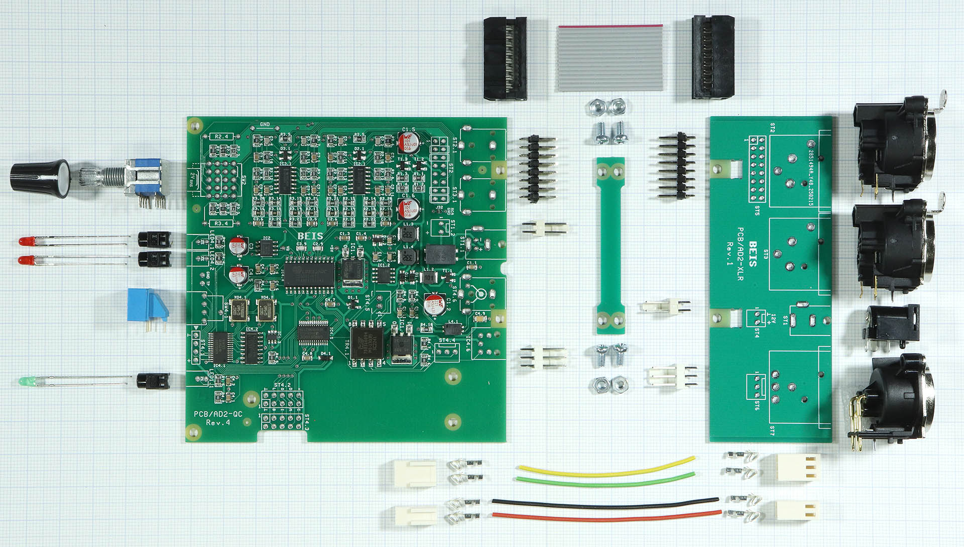
The photo shows all parts of the AD2-QP kit except for the housing.
Parts to be populated:
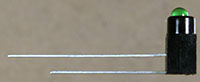 The LEDs for the operating voltage indicator (green) and overload indicator (2 x red):
A small circuit board is used to mechanically connect the two assemblies. They are screwed together with 4 pan-head screws M2.5x6 mm and nuts. The connecting circuit board can be screwed to the top or bottom side. I prefer the underside. There is of course some play in the holes for the screws. As a result, the two PCBs could be screwed together slightly offset from each other. Care should therefore be taken to ensure that the side edges of the PCBs are aligned. Experience has shown that it is slightly better if the play is used to make the distance between the PCBs larger.
Making the connection cables requires some experience, practice and suitable tools.
16 pin ribbon cable for the audio inputs:
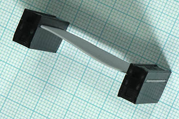 Included is a ribbon cable that is exactly 42.5 mm long and cut exactly at right angles. The IDC female connectors are pressed on so that the ends of the cable are exactly flush with the housings of the female connectors. The exact right angles are important here.
(It is completely unimportant, but I also make sure that the red marked wire on both female connectors corresponds to pin 1 (small arrow) and then also to pin 1 on the circuit boards).
Connection cable for supply voltage and AES3/EBU output:
The enclosed 0.25 mm² wires for the supply voltage (black, ground) and (red, +12 V) are cut to length to 70 mm, the two wires for the AES3/EBU output (yellow and green) are cut to length to 55 mm. After stripping approx. 3 mm of insulation, the spring contacts are crimped on using crimping pliers with an insert for 0.25 mm² wires. It should be checked in advance whether the crimping pliers are really suitable, i.e. whether the wires are really firmly connected to the spring contact after crimping.
The middle contact of the AES3/EBU connection is the digital ground and remains open. The ground connections of the XLR connection, i.e. shield and pin 1, are on the housing, which is connected to the analog ground.
The spring contacts are now inserted into the housing on one side until the barb prevents them from being pulled out.
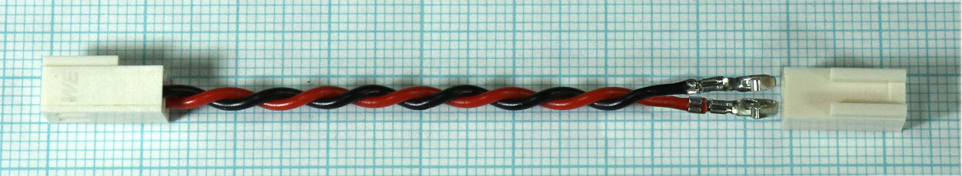 I prefer to twist the wires together so that they are "wrapped around each other" and not twisted in on themselves. Then they do not have the tendency to spring back, i.e. to "untwist".
The spring contacts on the other side can now also be inserted into the housings.
The polarity of the cable for the operating voltage is of course important and its coloring is common, but the polarity and coloring of the AES3/EBU connection is irrelevant. However, I prefer it to be uniform.
The 3 connecting cables are plugged into the modules.
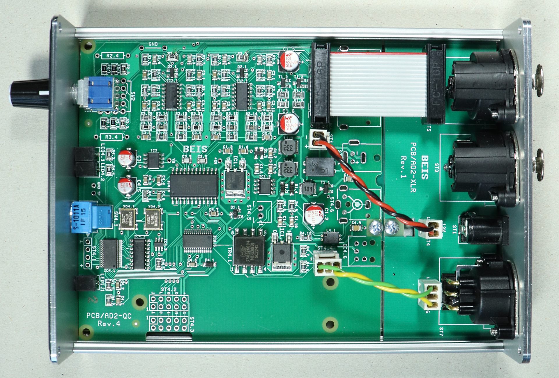
The AD2-QP is now basically ready for operation and can be tested.
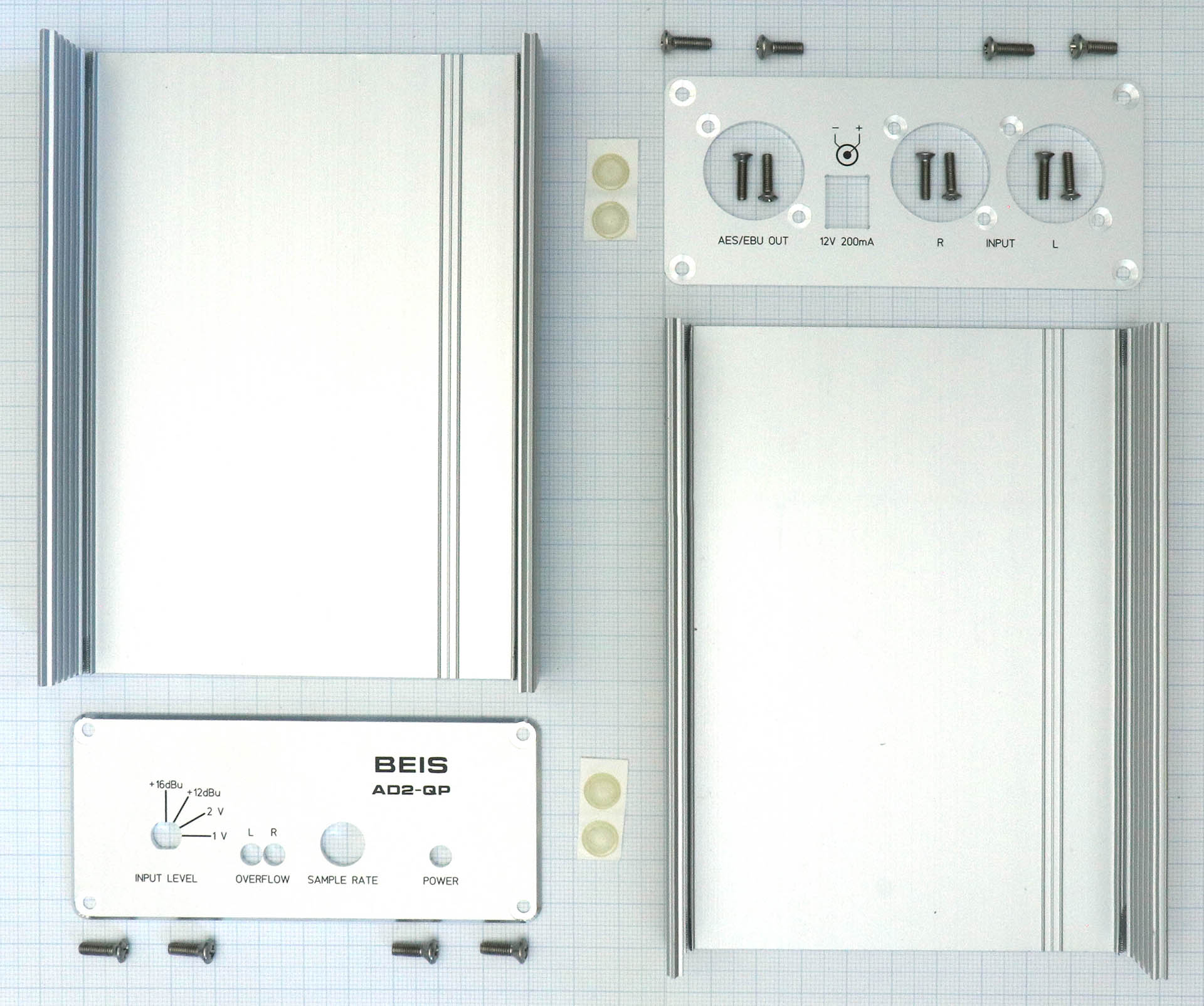
Picture: All parts for the housing of the AD2-QP (photo of a prototype with a housing height of 46 mm and incorrect and incomplete front panel labeling)
The assembly of the housing should be self-explanatory, but I would like to give a few hints:
The back plate is attached to the 3 XLR sockets with 6 M2.5x8 mm pan-head screws. Attention: When attaching the back plate, make sure that the power supply socket protrudes into the opening provided before screwing it on!
The lower housing shell (15 mm high) is slid onto the modules and screwed to the back plate using 2 M3x10 mm pan-head screws.
The front panel is placed on top and also screwed to the lower housing shell with 2 M3x10 mm pan-head screws. Attention: Here, too, care must be taken to ensure that the 3 LED holders protrude into the openings provided before screwing!
The upper housing shell (23 mm high) can be fitted and screwed in place with 4 M3x10 mm pan-head screws.
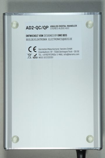
Finally, a product sticker and, if necessary, 4 housing feet should be glued under the housing:
The following settings can be made with the SAMPLE RATE switch:
| Setting | Sample Rate (kHz) |
Format | ||
| 0 | 48 | Professional | ||
| 1 | 12 | Professional | ||
| 2 | 16 | Professional | ||
| 3 | 22.05 | Professional | ||
| 4 | 24 | Professional | ||
| 5 | 32 | Professional | ||
| 6 | 44.1 | Professional | ||
| 7 | 48 | Professional | ||
| 8 | 64 | Professional | ||
| 9 | 88.2 | Professional | ||
| A | 96 | Professional | ||
| B | 176.4 | Professional | ||
| C | 192 | Professional | ||
| D | 32 | Consumer | ||
| E | 44.1 | Consumer | ||
| F | 48 | Consumer |
The 12 sample rates, whose digital audio signal is referred to as "Professional Format", are selected in position 0 - C. Position 0 corresponds to the situation where the sample rate switch is not fitted. The sample rate is then set to 48 kHz.
Positions D, E and F are referred to as "Consumer Format", where only 32 kHz, 44.1 kHz and 48 kHz can be selected. In consumer mode, the category code of the ADC is "General" (00hex) and copyright is not claimed.
With the INPUT LEVEL switch the input level UIN for 100% FS ("Full Scale") can be set to 4 levels:
For the +15 dBu switch position, the input level UIN for 100% FS can be set to a value between approx. 100 mVrms and +15 dBu. Two additional THT resistors RGain can be inserted in the slots provided for this purpose:
2 * UIN
RGain = ----------- kΩ
4.36V - UIN
The front panel label +15 dBu is then of course no longer correct. In principle, settings for even lower input levels than 100 mVrms (i.e. approx. 47 Ω) also work, but this is not recommended.
A simple function test should suffice as a final test. Some further information can be found in the article AD2-QC.
The measured values for the audio signals practically correspond to those of the AD24QS, as is to be expected due to the similar technology.
| Sampling rates | 12 different ones, 12 - 192 kHz | |
| Analog inputs | RCA, unbalanced, 180 kΩ | |
| Input sensitivity at 100% FS |
Switchable 1 Vrms | 2 Vrms | +12 dBu | +15 dBu Other gains for the setting +15 dBu are possible with resistors that can be retrofitted |
|
| Dynamic range |
117 dB A-weighted (typical) |
|
| THD | t. b. d. (AD24QS: typ. -120 dB @ -6 dB FS) | |
| Common Mode Rejection Ratio (CMRR) | > 60 dB, typ. 70 - 80 dB, range ±8 V | |
| Power Supply Rejection Ratio (PSRR) | ca. 100 dB bei 100 Hz | |
| Frequency response @ +0 / -3 dB | SR 12 kHz up to 96 kHz: 2 Hz - SR/2 SR 192 kHz: 2 Hz - 78 kHz |
|
| Digital audio outputs | S/PDIF (RCA), coaxial 75 Ω and optical (Toslink) | |
| Latency | 192 kHz: 46 µs 96 kHz: 126 µs 48 kHz: 310 µs 44.1 kHz: 275 µs |
|
| Power supply | 12 V DC (10 - 15 V), typ. approx. 100 mA, max. < 200 mA Protected against reverse polarity 2.1 / 5.5 mm hollow plug, lockable |
|
| Dimensions (L x W x H) | 144 mm x 105 mm x 38 mm (Housing only) |
|
| Weight | 370 g incl. housing |
The measured values listed above are from a sample device and cannot be guaranteed.
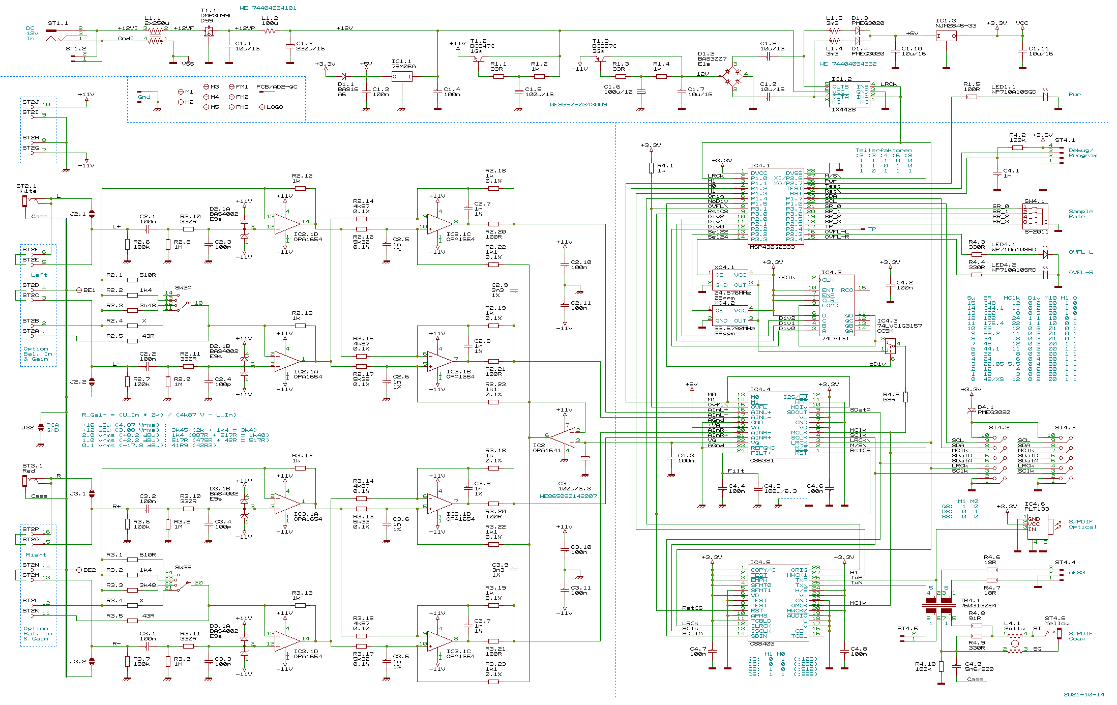
Finally here: The circuit diagram of the AD2-QC.
| Qty. | Part | |
| 1 | AD2-QC with SMDs | |
| 1 | PCB/AD2-XLR | |
| 1 | PCB/AD2-XLRX | |
| 1 | XLR NC3MBH | |
| 2 | XLR NC3FBH2 | |
| 1 | Power Jack 4840.2202 | |
| 2 | 2x08 pin Header 180° | |
| 2 | 16 pin IDC PFL16 Socket | |
| 1 | 16 pin Ribbon Cable, 42.5 mm | |
| 2 | WR-WTB Male Header 2p | |
| 2 | WR-WTB Male Header 3p | |
| 2 | WR-WTB Housing Female 2p | |
| 2 | WR-WTB Housing Female 3p | |
| 10 | WR-WTB Crimp Contact | |
| 2 | Wires 55 mm, 0.25 mm², green & yellow | |
| 2 | Wires 70 mm, 0.25 mm², black & red | |
| 1 | Switch SRBM/S1010 | |
| 1 | Knob | |
| 1 | LED WP710A10SGD | |
| 2 | LED WP710A10SRD/J4 | |
| 3 | LED Holder | |
| 1 | Hex Switch S1011A | |
| 4 | M2,5x6 DIN7985 (tallow-drop screw) | |
| 4 | Nut M2,5 |
| Qty. | Part | |
| 1 | Profile GB73 | |
| 1 | Profile GB48 | |
| 1 | Front Panel | |
| 1 | Rear Panel | |
| 8 | M3x10 A2 DIN966 (raised countersunk head) | |
| 6 | M2,5x8 A2 DIN966 (raised countersunk head) | |
| 4 | Bumpon SJ5302 |
The AD2-QP will soon be available as finished device with housing (possibly also as a kit) from Heroms GmbH.
| Last update: November 24th, 2025 | Questions? Suggestions? Email Me! | Uwe Beis |